Schematic | Circuit guide | Manual Wiring diagram | Electronic

Figurewiring Diagram Ethernet Crossover Cable

Posted by Unknown Wednesday, July 31, 2013 0 comments
Cat5e Wiring on An Ethernet And Phone Jack Using A Single Cat5e Cable   Mavromatic
An Ethernet And Phone Jack Using A Single Cat5e Cable Mavromatic.


Cat5e Wiring on Cat 5 Wiring Diagram For Home Networks  Security Systems And Phone
Cat 5 Wiring Diagram For Home Networks Security Systems And Phone.


Cat5e Wiring on Curt S Cat5 Wiring Diagram
Curt S Cat5 Wiring Diagram.


Cat5e Wiring on Cat5e Wiring
Cat5e Wiring.


Cat5e Wiring on Figure 4   Wiring Diagram For An Ethernet Crossover Cable
Figure 4 Wiring Diagram For An Ethernet Crossover Cable.


Cat5e Wiring on Wiring Diagram For Rj 45 Cat5e Cable   I T  On The Go Inc  Computer
Wiring Diagram For Rj 45 Cat5e Cable I T On The Go Inc Computer.


Cat5e Wiring on Palmetto Networks    A Professional Technology Company
Palmetto Networks A Professional Technology Company.


Cat5e Wiring on There Are Two Standard Cat5 And Cat6 Wiring Diagrams    I Use Cat5 B
There Are Two Standard Cat5 And Cat6 Wiring Diagrams I Use Cat5 B.


Cat5e Wiring on Diagram Of Correct Color Alignment For Making Cat5e Network Cable
Diagram Of Correct Color Alignment For Making Cat5e Network Cable.


Cat5e Wiring on Structured Wiring Retro   Install 1
Structured Wiring Retro Install 1.


Very Low Dropout Adjustable Breadboard Power Supply

Posted by Unknown 0 comments
This project details the design of a very low dropout adjustable power supply. A good power supply is essential to electronic projects. While there are many existing designs for adjustable power supplies, this one makes improvements that make it more useful for hobby designs

Very Low Dropout Adjustable Breadboard Power SupplyMIC2941 regulator has guaranteed 1.25A output
Low dropout, only 40mV - 400mV compared to 1.25V - 2.0V for LM317. This means you can use a wider range of output voltages including generating 3.3V from as low as 3.7V (such as 3 AAs or a lithium ion battery)!
Short circuit and overheating protection
Input diode to protect circuitry from negative voltages or AC power supplies.
2.1mm DC jack and terminal connector for voltage inputs
Two indicator LEDs for high and low voltages
Output selection switch to select from 3.3v, 5v and Adjustable
On-board potentiometer for adjusting voltage from 1.25V up to within 0.5V of the input voltage. (20V max)
On/Off switch for entire board
Very Low Dropout Adjustable Breadboard Power Supply Circuit Diagram

How much do the fuel tanks capacities and tank codes for the 1990 Chevrolet Cheyene 2500

Posted by Unknown 0 comments


How much do the fuel tanks capacities and tank codes for the 1990 Chevrolet Cheyene 2500?


Answer: The short bed is 26 gallon while the long bed is a 34 gallon. You can find the data in the owner’s manual under capacities. A sticker in the glove box should contain all of the RPO codes for your truck.

Voltage Regulators

Posted by Unknown Tuesday, July 30, 2013 0 comments
Voltage regulator integrated circuits are widely used in electronics. There are two main types of regulator: linear and switching. This page concerns the linear variety.
The idea of a regulator is simple: you place it between an irregular voltage source (such as a battery, a solar cell, or an unsmoothed DC supply) and a circuit which requires a constant supply voltage. Even if your circuit can work from an unsmoothed supply it may still be a good idea to use a regulator because built into it is a current limiting feature which will protect the supply when you accidently short it on your circuit.
The simplest regulator of all is called a three terminal regulator .

There is one connection for the unsmoothed input, one for the regulated output, and one for a common. They are obtainable for outputs of 5, 12, 15 or 24 volts, either positive or negative. You also have a choice of permissable current capability: most often 100mA or 1A.
For experimental or prototype work it may be too expensive to stock all 16 types mentioned above.

SW Converter for AM Radio

Posted by Unknown 0 comments
Apart from chucking it in the bin, what can you do with outdated AM automobile radio or clock radio in your junkbox? How about fliping it right into a crystal managed, secure, quick wave radio receiver, for a minimal funding in time and money? Read on. The coronary heart of the circuit shown here is an IC which works by the title NE602, NE612 or SA612. It is a double balanced mixer that features an oscillator that can be crystal-controlled, free working or even pushed externally from a PLL, and many others. It was once in the beginning designed for cellular telephones and is most probably to be had in junked car telephones from the tip. The NE602/612 accommodates a differential input amplifier (called a Gilbert Cell), an oscillator/buffer, a temperature compensated bias community and a energy regulator. Typical frequency response is in far more than 500 MHz for the input and 100 MHz for the oscillator.
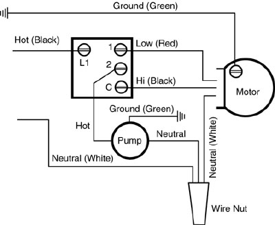
Circuit diagram :
SW Converter for AM Radio Circuit Diagram
 
Supply present is 2.4 mA and the absolute maximum provide voltage is 9 V. Input and output impedances are approx. 1.5 kΩ. As you'll find from the circuit diagram, the enter from the aerial is handed through a ten.7 MHz IF (intermediate frequency) transformer. This offers isolation from the aerial and cut backs the effect of sturdy local AM radio step forward.The transformer may also be salvaged from a dead FM radio or stereo or even the FM component to an previous clock radio. (The AM part is what we want to use anyway so ratting just a little from the FM section keeps cost). A selection of 10.7 MHz IF coils from Toko and other far-Eastern manufacturers may be used, together with the 94AES30465N and 94ANS30466N, but obtaining these as new phases may be more pricey than an entire radio rescued from the tip. There is on a standard basis a small capacitor under the IFT coil, between the pins. If so, do away with it by means of crushing it with a pair of pliers and ripping out the remains. The capacitor will no longer be wanted as we add an exterior one in step with the band wished. The input sign is fed into the balanced input of the IC.
 
The crystal is hooked up to pin 6. It oscillates at its fundamental frequency and that is mixed with the input signal giving a selection of outputs. The mixer output signal appears on pins four and 5. Here, handiest pin 5 is used for the output. By the way, the enters and outputs are interiorly biased with pull-up resistors, so there's no have to tie the unused pins to ground or energy. The 220 pF capacitor offers isolation to any DC into the AM radio aerial input. Note also that the same circuit can be used to increase the selection of an present short wave radio receiver in precisely the identical method. The AM radio is used as a tuneable intermediate frequency amplifier, with a tuning vary of about 1.6 MHz. You can are attempting different prices for C1 to get resonance on the NE602 input: a hundred and fifty pF for up to 5 MHz, forty seven pF for up to 8 MHz, and no capacitor for as a lot as 10 MHz. In apply however 33 pF will have to do for all ranges. Almost any crystal can be utilized. The creator tried many varieties from FT-243 WW2 surplus ones to 27 MHz, third overtone CB crystals. Every crystal tried worked. TV sub-carrier crystals work well, as do large oven varieties. Several crystals can additionally be linked through a switch, giving a convenient manner of swaping bands. Keep the leads to the swap as short as that that you can think of though to forestall radiation of the crystal oscillator. There are many tips on how to construct the circuit. You could make it right into an external metallic field that can be related to a quantity of radio’s, depending in your location. For instance, if you're a traveller, make it in a small box with an internal 9-volt battery, and leave sufficient wire on the output to wrap a few dozen flips across the clock radio in your Hotel room.


This gives you your quick-wave reception on the go. It can also be imaginable to construct the converter proper into the auto radio. Any form of development method can be used, from a small piece of perforated board that I used, to a extra problematic printed circuit board and even simply lash all of the small components beneath the IC socket. A small swap is additionally used to alter from AM to short-wave. Connect the circuit to the car radio with screened cable to stop or lessen the impact of robust station step forward. To couple the output of the converter to a radio with out an external AM aerial enter, wind several turns of wire round the interior ferrite rod aerial. As steered before, winding a dozen or so turns across the plastic radio case will additionally couple the converter to the radio. This will work at the fee of increased AM sign breakthrough. Connect the positive power lead to the switch on the radio so that it changees the converter on and off as well.

The quick-wave aerial can be 2 to a few meters of wire strung across the room, but better outcomes can be received with a outdoor aerial. The take a look at aerial was about one hundred meters lengthy and 10 meters high. At evening there is a lot of job on the short waves after darkish. Find a weak station round 1 MHz on the AM dial and alter the core of the IFT for minimal extent from the broadcast station. That’s the simplest alterment. SSB alerts can additionally be heard, but as no beat frequency oscillator is fitted, you hear the “duck talk” of the signal. The 10 kHz bandwidth of the radio means that on the ham bands, signals do overlap, however it also makes the broadcast stations sound higher as most of them do broadcast with cheap high quality audio. Digital tuned AM radios are on a regular basis no longer appropriate for the circuit as introduced, because the tuning steps are 9 or 10 kHz apart and we wish a lot smaller steps. The previous manually tuned varieties of automotive radio are what you wish to have. The idea of the circuit is to no lengthyer get too complicated, but to just experience listening on a simple, stable, low cost, brief wave receiver. Experiment and experience!


Author : P. Laughton, VK2XAN – Copyright: Elektor Electronics

Thermostat Transformer Jpgviews2387size

Posted by Unknown Monday, July 29, 2013 0 comments
Thermostat Wiring on 106 Honeywell Thermostat  106    China Thermostat
106 Honeywell Thermostat 106 China Thermostat.


Thermostat Wiring on Name  Thermostat Transformer Jpgviews  2387size  130 4 Kb
Name Thermostat Transformer Jpgviews 2387size 130 4 Kb.


Thermostat Wiring on Converting To Automag Using Teo Wire Thermostats Diagram
Converting To Automag Using Teo Wire Thermostats Diagram.


Thermostat Wiring on Knock  4 000 Off Your Utility Bill   Use Time Settings For Heat  3
Knock 4 000 Off Your Utility Bill Use Time Settings For Heat 3.


Thermostat Wiring on Boiler Supply From Heat Bank Thermal Store Wiring Centre
Boiler Supply From Heat Bank Thermal Store Wiring Centre.


Thermostat Wiring on Rsk 2 Wiring Diagram
Rsk 2 Wiring Diagram.


Thermostat Wiring on Hi I Have A Honeywell St7100 Fitted Controlling My Central
Hi I Have A Honeywell St7100 Fitted Controlling My Central.


Thermostat Wiring on Free 1 Heat   1 Cool Thermostat   Horizontal   White Rodgers 1f56n 444
Free 1 Heat 1 Cool Thermostat Horizontal White Rodgers 1f56n 444.


Thermostat Wiring on Honeywell Store   Honeywell Rth6350d 5 2 Programmable Thermostat
Honeywell Store Honeywell Rth6350d 5 2 Programmable Thermostat.


Thermostat Wiring on Honeywell Thermostat Wiring Diagram   Electrical Reply
Honeywell Thermostat Wiring Diagram Electrical Reply.


Build an Audio notch filter 2

Posted by Unknown Thursday, July 25, 2013 0 comments
 Build an Audio notch filter 2 Circuit Diagram. With the circuit shown here the response at one octave off tune is within 10% of the far out response: notch sharpness may be increased or reduced by reducing or increasing.respectively the 68 ohm resistor. Linearity tracking of R8 and R9 has no effect on notch depth. The signals at HP and LP are always in antiphase, notch will always be very deep at the tuned frequency, despite tolerance variations in R6-9 and C2, C3. 

 
 Build an Audio notch filter 2 Circuit Diagram


 Build an Audio notch filter 2 Circuit Diagram

13 8Vdc 2A Regulated Power Supply Circuit Diagram

Posted by Unknown 0 comments
This 13.8Vdc 2A Regulated Power Supply Circuit Diagram consists of step-down transformer Tl, a full-wave rectifier bridge (D1 through D4), and a filtering regulator circuit made up of Cl, C2, Rl, R2, R8, D5, and Ql, When 120 Vac is provided, the neon-lamp assembly LI lights up, and transformer Tl changes 120 Vac to about 28 Vac. 

The rectifier bridge, )1 through D4, rectifies the ac into pulsating dc, which is then filtered by Cl. Capacitor Cl acts as a storage capacitor. Zener diode 1)5 keeps the voltage constant across the base of Darlington regulator Ql, causing constant voltage across resistor R3 and the (+) and (-) output terminals, where the load is connected. Fuse F2 is used to open (blow), if the current through the output terminals is too high. Make sure to take proper precautions when using projects powered by 120 Vac.

 13.8Vdc 2A Regulated Power Supply Circuit Diagram


13.8Vdc 2A Regulated Power Supply Circuit Diagram