Schematic | Circuit guide | Manual Wiring diagram | Electronic
Showing posts with label lighting. Show all posts

VGA Background Lighting

Posted by Unknown Sunday, December 22, 2013 0 comments
More and more people are using a PC (conventional or notebook) to view films. The VGA output can be used to provide a matching ‘Ambilight’ effect for this. If you restrict your-self to a single RGB LED, you can also draw the power for this circuit from the VGA connector, along with the RGB signals.

The following pins of the 15-way VGA connector (three rows of five pins) are used for  this circuit:

  • Pin 1:  Red video signal 
  • Pin 2:  Green video signal 
  • Pin 3:  Blue video signal 
  • Pin 5:  GND 
  • Pin 9:  +5 V

The video signals for the red, green and  blue channels are available at the RGB out-puts. These signals have an amplitude of 1 to 1.35 V, and they output the screen imagery at the rate of dozens of frames per second. This produces the visible image on the screen. The circuit described here drives an RGB LED according to the average values of each of these three signals. Of course, this is not a full-fledged ‘Ambilight’ system, but the RGB LED will produce a nice green light during a  football match or an orange hue if a sunset is shown on the screen.

VGA Background Lighting Circuit Diagram

VGA Background Lighting-Circuit Daigram

A sawtooth generator is built around IC1 and T1. It supplies a nice sawtooth signal to opamp IC2a via R6. The frequency of the sawtooth signal is approximately 850 Hz, and its amplitude ranges from 1.6 to 3.4 V. IC2A subtracts approximately 1.6 V from this due to voltage divider R4/R5. After this, voltage  divider R10/R11 reduces the peak value of the sawtooth to around 1.35 V. The resulting sawtooth signal is buffered by IC2b and  used to drive the three comparators in IC3. The level of the red video signal is averaged  by the R12/C2 network. IC3a constantly com-pares the previously generated sawtooth signal with the average value of the red video  signal. If the image has a high red content, the output of IC3a will be logic Low a good deal of the time, while with a low red content  it will be Low less often. This comparator circuit thus implements a PWM driver for the red LED. The same arrangement is used for the green and blue channels.
Note that with a notebook computer you always have to enable the VGA first, usually by pressing Fn-F5. If you use a desktop or tower PC, you can tap off the video signals from an adapter connected between the video cable and the monitor.

You can also use several LEDs or a LED strip (available from Ikea and other sources) in place of a single RGB LED. In this case you will need an external power supply for the LEDs, but the control circuit can still be powered from the PC. If you use multiple LEDs or a LED strip, connect the cathodes (negative leads) of the LEDs to the comparator outputs of IC3 as shown on the schematic diagram, and connect all the anodes (positive leads) to the external power supply. Resistors R15–R17 are often already integrated in the LED strip. There’s no harm in using an external supply with a higher working voltage, such as 12 V. Remember to connect the ground terminal of the external supply to the ground of the control circuit.

IC3 can handle a current of 15 mA on each  output. If this is not enough, swap the connections to the inverting and non-inverting inputs of the three comparators in IC3 and  connect their outputs to the bases of three  BC547 transistors. Connect a 10-kΩ resistor between each base and the positive supply  line (+5 V). Connect the emitter of each transistor to ground, and connect the collector  to the LED strip. A BC547 can switch up to  100 mA with this arrangement, and a BC517  can handle up to 500 mA.


Smart Lighting in the Enterprise

Posted by Unknown Thursday, September 12, 2013 0 comments
Daylight harvesting is becoming increasingly important in the design and implementation of commercial lighting systems. Being able to integrate the natural light from windows with flexible, controllable sources of lighting helps improve the work environment and cut energy bills.
Smart Lighting in the Enterprise
Being able to have closer control of the lighting systems in a commercial environment is a key element to this strategy and energy harvesting can play an important role. Being able to have flexible placement of control pads for a commercial lighting system is an important requirement as office space is regularly reconfigured as existing clients grow and change their requirements and new clients have new requirements.

Simple Lighting Surge Protector Circuit

Posted by Unknown Thursday, April 11, 2013 0 comments
GDT’s are special type of gas filled tubes used for wide range of electronic/electrical circuits for providing protection against lightning and other power surges.  These tubes basically has two electrodes that are kept inside a gas filled closed envelope. In case of electronic applications, the container is mostly ceramic in nature. For high grade electrical applications military tubes are used. The electrical characteristics of this tubes depends on the pressure and composition of gas, and the distance between the two electrodes contained inside. The most commonly used gases in GDT’s are given below.

1) Hydrogen gases
2) Deuterium gases
3) Noble gases
4) Elemental vapors (metals and nonmetals)
5) Other gases
6) Insulating gases
An image of a ceramic discharge tube is shown below. Take a look.

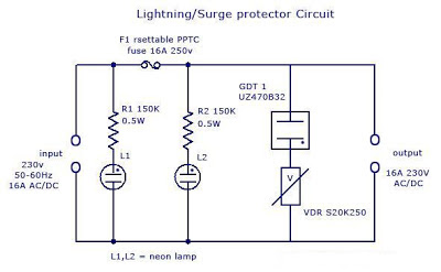
There will be conduction inside the GDT’s due to ionization of gas molecules. Each GDT have a specific voltage and current rating. A simple lightning protector circuit is given below.

Lighting/Surge Protector Circuit

In power lines, usually large amount of voltage is induced (typically very short time with high amplitude) due to lightning (direct or indirect strike) or Transients*
* (Transients caused by other equipments are usually caused by the discharge of stored energy in inductive and capacitive components. Electric motors, such as those used in elevators, heating, air conditioning, refrigeration or other inductive loads, can create a continuous stream of 250V to 1000V transients. DC motor drives, variable speed AC motor drives, DC power supply switching, and portable power tools are other sources of transients.)

Lightning protection circuit:

Simple Lighting Surge Protector Circuit

The basic surge suppression circuit shown below consists of a VDR** (Voltage Dependent Resistor) and gas surge suppressor (GDT) connected in series. The protection circuit is connected between live and mains lead. Normally no current flows through GDT and VDR1. When   the voltage between the terminals is higher than the sum of voltage ratings of GDT and VDR1 (here both GDT UZ470B and VDR S20K250 has 250v 16A rating), current starts to flow through those components. 

If more the voltage rises then more current starts to flow through GDT and VDR1.When the current is normal, the circuit is reset and resumes it’s functioning. Thus the current cannot be raised much over that predetermined value. When the voltage again goes back to normal values G1 and VDR1, the conducting stops and the circuit remains normal.  If the flowing current is more than the specified value of main self-resettable fuse, the fuse will break and the circuit will be protected. After the current is normal, the fuses resets and continue its functioning (protection against short circuit and overload). 

The circuit is designed to protect sensitive electronic devices against overvoltage transients in normal mains voltage and overload/ short circuit. Two neon pilot lamps are also provided with the circuit diagram to show the status of input and load supply.

(**A VDR (Voltage Dependent Resistor) is an electronic component with a “diode-like” nonlinear current–voltage characteristic. The name is a portmanteau of variable resistor.  VDRs are often used to protect circuits against excessive transient voltages by incorporating them into the circuit in such a way that, when triggered, they will shunt the current created by the high voltage away from the sensitive components. A VDR is also known as Voltage Dependent Resistor or VDR. A VDR’s function is to conduct significantly increased current when voltage is excessive.)

Voltage Dependent Resistor

Advantages:

1)      Normal working voltage = 230v AC/DC
2)      Maximum current rating=16A
3)      Cut-off current =16A
4)      Cut-off voltage= >300v R.M.S
5)      Protection against overloads
6)      Protection for short circuit

Applications:

1)      Protection for sensitive components
2)      Protection for motor devices
3)      Telephone line protection
4)      SMPS protection