Rotor Earth Fault Relay
Sunday, May 26, 2013
0
comments
The Rotor Protection relay is used in synchronous motors and generators to identify the presence of an earth fault in the rotor winding. While the winding in the rotor is insulated from the ground during normal operation, the Rotor is subjected tostresses due to vibration, heat, etc. These stresses can cause the winding to give way in a particular place and the winding can get earthed.
The currents produced during a rotor earth fault can cause excessive vibration and disturb the magnetic balance inside thealternator. These forces can cause the rotor shaft to become eccentric and in extreme cases cause bearing failure.
Hence, it is necessary that any earthing in the rotor is detected at the earliest. In slip ring rotors, carbon deposits on the slip rings may compromise the insulation resistance of the rotor. Hence, the slip rings need to be inspected for any deposits. The Rotor Earth Fault Protection Device consists of a current injection device which applies an AC voltage to the rotor winding by means of a slip ring fitted on the rotor. The current is applied to the rotor through a coupling capacitor. In the normal condition, the system is floating and the current flowing through the device is zero as the resistance is high. When a fault occurs, the current increases causing the relay to operate. The relay can be configured for alarm or trip depending on the criticality.
 Ground fault interrupters are designed to protect from electrical shock by interrupting a household circuit when there is a difference in the currents in the "hot" and neutral wires. Such a difference indicates that an abnormal diversion of current from the "hot" wire is occuring. Such a current might be flowing in the ground wire, such as a leakage current from a motor or from capacitors. More importantly, that current diversion may be occurring because a person has come into contact with the "hot" wire and is being shocked. When a circuit is functioning normally, all the return current from an appliance flows through the neutral wire, so the presence of a difference between "hot" and neutral currents represents a malfunction which in some circumstances could produce a dangerous or even lethal shock hazard.
The "hot" and neutral wires are passed through the sensing coil so that the currents in the two wires at any instant are traveling in opposite directions, giving a net zero current in the coil if the two currents are exactly equal. Since a current-carrying wire produces an AC magnetic field external to the wire, a non-zero current would induce a voltage in the sensing coil. The sensing coil is wound longitudinally to capture more of the wires magnetic field and therefore be a more sensitive net current detector. Even so, the difference that it is supposed to detect is quite small. The GFI is designed to trip when there is more than 5 milliamperes of leakage current out of the normal pathway.
he neutral return would then have 5 mA less current than the "hot" wire, but that might be out of a 20A load. So the circuit would have to detect a 0.025% deviation from 20A return current. Fortunately, comparator circuits such as an op-amp comparator are quite capable of detecting such differences. The voltage in the sensor coil is rectified and applied to the input of the sensitive comparator.
The comparator activates a trip coil which opens both the "hot" and neutral wires. If all circuits were wired with correct polarity, opening the "hot" wire would be sufficient, but since it is not uncommon for them to be accidentally wired backward, it is prudent to interrupt both leads.
It is common household practice to wire several receptacles on a given circuit. A single GFI at the circuit panel will protect the entire collection of receptacles since a difference between "hot" and neutral current at any one of them will cause a difference at the GFI. A single GFI at one receptacle would not protect the entire circuit.
Because of the great sensitivity of the detection of current differences, GFIs are prone to nuisance tripping in certain applications. A rather common practice in some areas is to have a freezer on the carport, and carport receptacles are sometimes wired with GFIs. Under moist conditions you can sometimes get enough leakage current to trip the GFI, and persons come back to find their freezer thawed out. A necessary safety precaution in bathrooms and near pools, they are sometimes quite troublesome in outdoor applications where reliable power is needed. John de Armond has a good discussion of other circumstances which lead to nuisance tripping, particularly with campers and recreational vehicles.
While a single earthing in the winding is not immediately damaging. It sets the stage for damage if a second failure should occur. The second earthing can cause a short-circuit through the rotor causing extensive damage to the rotor and the winding.
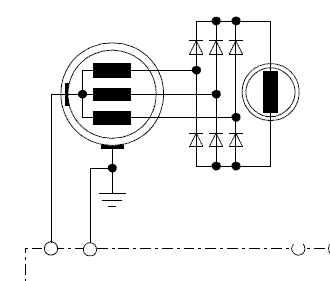 |
| Rotor Earth Fault Relay |
Hence, it is necessary that any earthing in the rotor is detected at the earliest. In slip ring rotors, carbon deposits on the slip rings may compromise the insulation resistance of the rotor. Hence, the slip rings need to be inspected for any deposits. The Rotor Earth Fault Protection Device consists of a current injection device which applies an AC voltage to the rotor winding by means of a slip ring fitted on the rotor. The current is applied to the rotor through a coupling capacitor. In the normal condition, the system is floating and the current flowing through the device is zero as the resistance is high. When a fault occurs, the current increases causing the relay to operate. The relay can be configured for alarm or trip depending on the criticality.

Ground Fault Interrupter
0
comments
Ground fault interrupters are designed to protect from electrical shock by interrupting a household circuit when there is a difference in the currents in the "hot" and neutral wires. Such a difference indicates that an abnormal diversion of current from the "hot" wire is occuring. Such a current might be flowing in the ground wire, such as a leakage current from a motor or from capacitors. More importantly, that current diversion may be occurring because a person has come into contact with the "hot" wire and is being shocked. When a circuit is functioning normally, all the return current from an appliance flows through the neutral wire, so the presence of a difference between "hot" and neutral currents represents a malfunction which in some circumstances could produce a dangerous or even lethal shock hazard.
The "hot" and neutral wires are passed through the sensing coil so that the currents in the two wires at any instant are traveling in opposite directions, giving a net zero current in the coil if the two currents are exactly equal. Since a current-carrying wire produces an AC magnetic field external to the wire, a non-zero current would induce a voltage in the sensing coil. The sensing coil is wound longitudinally to capture more of the wires magnetic field and therefore be a more sensitive net current detector. Even so, the difference that it is supposed to detect is quite small. The GFI is designed to trip when there is more than 5 milliamperes of leakage current out of the normal pathway.
he neutral return would then have 5 mA less current than the "hot" wire, but that might be out of a 20A load. So the circuit would have to detect a 0.025% deviation from 20A return current. Fortunately, comparator circuits such as an op-amp comparator are quite capable of detecting such differences. The voltage in the sensor coil is rectified and applied to the input of the sensitive comparator.
The comparator activates a trip coil which opens both the "hot" and neutral wires. If all circuits were wired with correct polarity, opening the "hot" wire would be sufficient, but since it is not uncommon for them to be accidentally wired backward, it is prudent to interrupt both leads.
It is common household practice to wire several receptacles on a given circuit. A single GFI at the circuit panel will protect the entire collection of receptacles since a difference between "hot" and neutral current at any one of them will cause a difference at the GFI. A single GFI at one receptacle would not protect the entire circuit.
Because of the great sensitivity of the detection of current differences, GFIs are prone to nuisance tripping in certain applications. A rather common practice in some areas is to have a freezer on the carport, and carport receptacles are sometimes wired with GFIs. Under moist conditions you can sometimes get enough leakage current to trip the GFI, and persons come back to find their freezer thawed out. A necessary safety precaution in bathrooms and near pools, they are sometimes quite troublesome in outdoor applications where reliable power is needed. John de Armond has a good discussion of other circumstances which lead to nuisance tripping, particularly with campers and recreational vehicles.
Popular Posts
-
 The CDI ignition circuit produces a spark from an ignition coil by discharging a capacitor across the primary of the coil. A 2uF capacitor i...
 -
 GDT’s are special type of gas filled tubes used for wide range of electronic/electrical circuits for providing protection against lightn...
 -
 The series of Universal PIC Programmer can be used with software IC-Prog 1:05. Universal PIC programmer circuit is very simple with BC337 tr...