Schematic | Circuit guide | Manual Wiring diagram | Electronic
Showing posts with label relay. Show all posts

Sound Activated Lamp Relay Switch

Posted by Unknown Monday, September 2, 2013 0 comments
This simple circuit shown int the schematic diagram actives the switch using sound. We can use this circuit for various applications, such as automatic (sound-controlled) disco light or car’s LED light show.  The Q1 amplify the audio from mic. The R1 is used to adjust the peak of signal to greater than about 0.7 volts, act as sensitivity adjuster. A certain level, the signal coming from microphone, after amplification by Q1, will trigger the SCR and light lamp I1. If we change the lamp with a relay, then we can get a sound-activated relay/switch, which can be used to control more powerful / high wattage high voltage lamps.

Sound Activated Lamp-Relay Switch Circuit Diagram


If we use a relay, place a 1N4007 diode in parallel with the relay coil to prevent the back-emf from  relay coil destroying the SCR.

Reducing Relay Power Consumption

Posted by Unknown Saturday, August 3, 2013 0 comments
Relays are often used as electrically controlled switches. Unlike transistors, their switch contacts are electrically isolated from the control input. On the other hand, the power dissipation in a relay coil may be unattractive for battery-operated applications. Adding an analogue switch lowers the dissipation, allowing the relay to operate at a lower voltage. The circuit diagram shows the principle. Power consumed by the relay coil equals V2/RCOIL. The circuit lowers this dissipation (after actuation) by applying less than the normal operating voltage of 5 V. Note that the voltage required to turn a relay on (pickup voltage)is usually greater than that to keep it on (dropout voltage).


In this respect the relay shown has specifications of 3.5 and 1.5V respectively, yet the circuit allows it to operate from an intermediate supply voltage of 2.5V. Table 1 compares the relay’s power dissipation with fixed operating voltages across it, and with the circuit shown here in place. The power savings are significant. When SW1 is closed, current flows through the relay coil, and C1 and C2 begin to charge. The relay remains inactive because the supply voltage is less than its pickup voltage. The RC time constants are such that C1 charges almost completely before the voltage across C2 reaches the logic threshold of the analogue switch inside the MAX4624 IC.


When C2 reaches that threshold, the on-chip switch connects C1 in series with the 2.5V supply and the relay coil. This action causes the relay to be turned on because its coil voltage is then raised to 5 V, i.e., twice the supply voltage. As C1 discharges through the coil, the coil voltage drops back to 2.5 V minus the drop across D1. However, the relay remains on because the resultant voltage is still above the dropout level (1.5 V). Component values for this circuit depend on the relay characteristics and the supply voltage. The value of R1, which protects the analogue switch from the initial current surge through C1, should be sufficiently small to allow C1 to charge rapidly, but large enough to prevent the surge current from exceeding the specified peak current for the analogue switch.

The switch’s peak current (U1) is 400mA, and the peak surge current is IPEAK = (VIN – VD1) / R1 + RON) where RON is the on-resistance of the analogue switch (typically 1.2 Ω). The value of C1 will depend on the relay characteristics and on the difference between VIN and the pickup voltage. Relays that need more turn-on time requires larger values for C1. The values for R2 and C2 are selected to allow C1 to charge almost completely before C2’s voltage reaches the logic threshold of the analogue switch. In this case, the time constant R2C2 is about seven times C1(R1 + RON). Larger time constants increase the delay between switch closure and relay activation. The switches in the MAX4624 are described as ‘guaranteed break before make’. The opposite function, ‘make-before break’ is available from the MAX4625. The full datasheets of these interesting ICs may be found at http://pdfserv.maxim-ic.com/arpdf/MAX4624-MAX4625.pdf

Rotor Earth Fault Relay

Posted by Unknown Sunday, May 26, 2013 0 comments
The Rotor Protection relay is used in synchronous motors and generators to identify the presence of an earth fault in the rotor winding. While the winding in the rotor is insulated from the ground during normal operation, the Rotor is subjected tostresses due to vibration, heat, etc. These stresses can cause the winding to give way in a particular place and the winding can get earthed.
 While a single earthing in the winding is not immediately damaging. It sets the stage for damage if a second failure should occur. The second earthing can cause a short-circuit through the rotor causing extensive damage to the rotor and the winding.
Rotor Earth Fault Relay
The currents produced during a rotor earth fault can cause excessive vibration and disturb the magnetic balance inside thealternator. These forces can cause the rotor shaft to become eccentric and in extreme cases cause bearing failure.

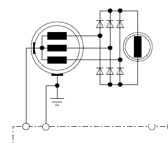
 Hence, it is necessary that any earthing in the rotor is detected at the earliest. In slip ring rotors, carbon deposits on the slip rings may compromise the insulation resistance of the rotor. Hence, the slip rings need to be inspected for any deposits. The Rotor Earth Fault Protection Device consists of a current injection device which applies an AC voltage to the rotor winding by means of a slip ring fitted on the rotor. The current is applied to the rotor through a coupling capacitor. In the normal condition, the system is floating and the current flowing through the device is zero as the resistance is high.  When a fault occurs, the current increases causing the relay to operate. The relay can be configured for alarm or trip depending on the criticality.

Electronic Fuse Employs A Relay

Posted by Unknown Tuesday, April 30, 2013 0 comments
while many power supplies can be set to limit their output current to a defined level, to protect the circuit they are powering, no such protection is available if you are powering a circuit from a battery. If a fault develops, the circuit can blow before you have a chance to disconnect it. Of course, you can fit a fuse in series with the supply line to the circuit under test but it will blow if a fault develops. Or perhaps it won’t blow sufficiently quickly to protect the circuit. And repeatedly having to replace fuses becomes a nuisance as well.

Electronic Fuse Employs A Relay
The alternative is to use an electronic fuse. This circuit uses a relay to make and break the circuit. The current drain of the circuit under test is monitored by a 1O 2W resistor which is placed in series with the supply line. The voltage across this 1O resistor is monitored by op amp IC1a which has an adjustable gain of between 11 and 16, as set by trimpot VR1. The resultant DC voltage from pin 1 of IC1a is fed to pin 5 of IC1b which is configured as a comparator. Trimpot VR2 provides an adjustable voltage reference to pin 6 of IC1b and this is compared with the amplified signal from IC1a.

If IC1b’s threshold is exceeded, its pin 7 goes high and this is fed to Schmitt trigger inverter IC2a which then “sets” the RS flipflop comprising gates IC2c & IC2d. Pin 11 of IC2d then goes high to turn on transistor Q2 and LED1 while pin 4 of IC2b also goes high to turn on Q1 and the relay which then disconnects the load. The circuit stays in this state until the RS flipflop is reset by pushing switch S1. Capacitor Cx, across the feedback resistance of IC1a, is used to simulate a slow-blow or fast-blow fuse and can be selected by trial and error. Changing the gain of IC1a or the value of the sensing resistor changes the fuse rating of the circuit.