Schematic | Circuit guide | Manual Wiring diagram | Electronic
Showing posts with label cable. Show all posts

Ethernet Cable Wiring

Posted by Unknown Friday, August 16, 2013 0 comments
Ethernet Wiring on Ethernet Cable Wiring
Ethernet Cable Wiring.


Ethernet Wiring on Connectlink Wireless   Ethernet Wiring Diagram
Connectlink Wireless Ethernet Wiring Diagram.


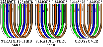
Ethernet Wiring on Ethernet Cable Wiring Diagram Straight Lg
Ethernet Cable Wiring Diagram Straight Lg.


Ethernet Wiring on Ethernet Cable Wiring Diagram Crossover Lg
Ethernet Cable Wiring Diagram Crossover Lg.


Ethernet Wiring on Crossover Ethernet Cable
Crossover Ethernet Cable.


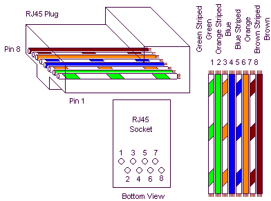
Ethernet Wiring on Ethernet Straight Through Cable Pin Configuration
Ethernet Straight Through Cable Pin Configuration.


Ethernet Wiring on Wireless Networks Vs  Ethernet Networks  Is There Still A Debate
Wireless Networks Vs Ethernet Networks Is There Still A Debate.


Ethernet Wiring on Gigabit Ethernet Uses Cable In The Same Way As 100base T Ethernet
Gigabit Ethernet Uses Cable In The Same Way As 100base T Ethernet.


Ethernet Wiring on How To Make Patch   Crossover Network Cables
How To Make Patch Crossover Network Cables.


Ethernet Wiring on Ethernet Cable To Modem Router
Ethernet Cable To Modem Router.


Figurewiring Diagram Ethernet Crossover Cable

Posted by Unknown Wednesday, July 31, 2013 0 comments
Cat5e Wiring on An Ethernet And Phone Jack Using A Single Cat5e Cable   Mavromatic
An Ethernet And Phone Jack Using A Single Cat5e Cable Mavromatic.


Cat5e Wiring on Cat 5 Wiring Diagram For Home Networks  Security Systems And Phone
Cat 5 Wiring Diagram For Home Networks Security Systems And Phone.


Cat5e Wiring on Curt S Cat5 Wiring Diagram
Curt S Cat5 Wiring Diagram.


Cat5e Wiring on Cat5e Wiring
Cat5e Wiring.


Cat5e Wiring on Figure 4   Wiring Diagram For An Ethernet Crossover Cable
Figure 4 Wiring Diagram For An Ethernet Crossover Cable.


Cat5e Wiring on Wiring Diagram For Rj 45 Cat5e Cable   I T  On The Go Inc  Computer
Wiring Diagram For Rj 45 Cat5e Cable I T On The Go Inc Computer.


Cat5e Wiring on Palmetto Networks    A Professional Technology Company
Palmetto Networks A Professional Technology Company.


Cat5e Wiring on There Are Two Standard Cat5 And Cat6 Wiring Diagrams    I Use Cat5 B
There Are Two Standard Cat5 And Cat6 Wiring Diagrams I Use Cat5 B.


Cat5e Wiring on Diagram Of Correct Color Alignment For Making Cat5e Network Cable
Diagram Of Correct Color Alignment For Making Cat5e Network Cable.


Cat5e Wiring on Structured Wiring Retro   Install 1
Structured Wiring Retro Install 1.


Rj45 Cable Tester

Posted by Unknown Friday, May 31, 2013 0 comments
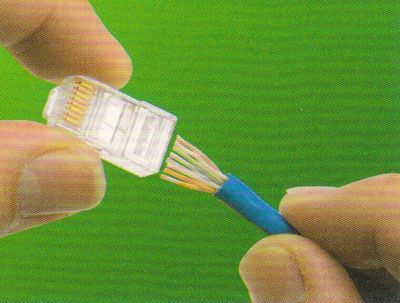
Cat5 Wiring on On The Crimping Tool To Permanently Attach The Rj45 To The Cat5 Cable
On The Crimping Tool To Permanently Attach The Rj45 To The Cat5 Cable.


Cat5 Wiring on The Formal Cat5 Definition Reserves The Extra 4 Wires So
The Formal Cat5 Definition Reserves The Extra 4 Wires So.


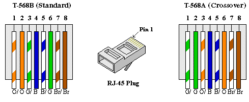
Cat5 Wiring on Figure 4   Wiring Diagram For An Ethernet Crossover Cable
Figure 4 Wiring Diagram For An Ethernet Crossover Cable.


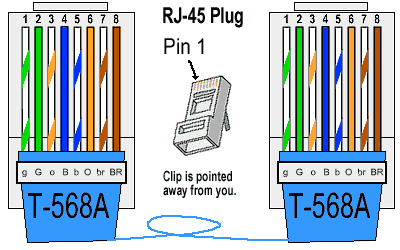
Cat5 Wiring on There Are Two Wiring Standards For These Cables  Called T 568a And T
There Are Two Wiring Standards For These Cables Called T 568a And T.


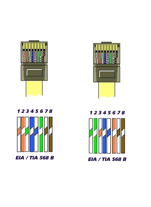
Cat5 Wiring on Category 5 Patch Cable In T568b Wiring
Category 5 Patch Cable In T568b Wiring.


Cat5 Wiring on Home Phone Wiring Diagram Using Cat5 Cable Here  Source  Scribd Com
Home Phone Wiring Diagram Using Cat5 Cable Here Source Scribd Com.


Cat5 Wiring on Home Network Wiring Diagram
Home Network Wiring Diagram.


Cat5 Wiring on How To Make A Rj45 Cable Tester
How To Make A Rj45 Cable Tester.


Cat5 Wiring on How To Guide  Creating Cat 5 Utp Ethernet Crossover Cable   How To
How To Guide Creating Cat 5 Utp Ethernet Crossover Cable How To.


Cat5 Wiring on Cat5 Wiring
Cat5 Wiring.


Bhagwan Photoscat5 Cable Wiring Diagram

Posted by Unknown Thursday, May 30, 2013 0 comments
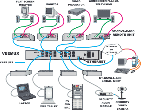
Cat5 Wiring on Cat5 Av Matrix Switches  Cat5 Audio Video Matrix Switch Solutions
Cat5 Av Matrix Switches Cat5 Audio Video Matrix Switch Solutions.


Cat5 Wiring on Category 5 Utp Patch Cable Standard Eia Tia 568a
Category 5 Utp Patch Cable Standard Eia Tia 568a.


Cat5 Wiring on See The Correct Wire Mapping Of A Cat5 Cable Straight And Crossover
See The Correct Wire Mapping Of A Cat5 Cable Straight And Crossover.


Cat5 Wiring on Bhagwan Photos  Cat5 Cable Wiring Diagram
Bhagwan Photos Cat5 Cable Wiring Diagram.


Cat5 Wiring on Ftp Cat5 Cat5e Solid Cable   China Ftp Cat5  Cat5e Solid Cable
Ftp Cat5 Cat5e Solid Cable China Ftp Cat5 Cat5e Solid Cable.


Cat5 Wiring on Diagram Of Correct Color Alignment For Making Cat5e Network Cable
Diagram Of Correct Color Alignment For Making Cat5e Network Cable.


Cat5 Wiring on Wiring Panel   Structured Home Wiring
Wiring Panel Structured Home Wiring.


Cat5 Wiring on Ethernet Cable Connection Between The Dsl Modem And The Netgear Hub
Ethernet Cable Connection Between The Dsl Modem And The Netgear Hub.


Cat5 Wiring on Cat5 Ethernet Cable   Pharos Testbed Wiki
Cat5 Ethernet Cable Pharos Testbed Wiki.


Cat5 Wiring on Coaxial Cables  Amphenol Connectors  Phone Cable  Network Cables
Coaxial Cables Amphenol Connectors Phone Cable Network Cables.


USB cable signals

Posted by Unknown Saturday, April 6, 2013 0 comments
USB cable consists of 4 wires plus a conductor wire wrapping, such as the protectors are usually found in the audio cable. Cable number 1 is used to channel resources to the voltage of 5 volts, if necessary USB devices may draw power from this line and should not exceed 100 mA. Computer equipped with USB capability, is required to provide power at 100 mA for this purpose. USB devices that require more power than the aforementioned provisions, must provide their own resources for the purposes work equipment.


The USB cable signals

Number 4 is the ground cable as a back channel source voltage of 5 volts. Cable number 2 and number 3 is used for signal transmission. No. 2 cable and cable called D-3 numbers called D, the voltage on the two channels is changed between 0 Volt and 3.3 Volt. Digital signal is sent through the two channels are said to be difference signal, which means that the signal digital 0 or 1 is not declared to the magnitude of the voltage on the channel to the ground, as well as digital signals used in the IC TTL (transistor Transitor Logic) or the RS232 channel.

Digital signal is expressed by the voltage difference between the two cables. If the voltage on the D channel is higher than the voltage at D-channel, then the information transmitted digital signal is 1 , otherwise the digital signal 0 is expressed by the voltage at D <voltage at D-. To distinguish the speed of data transmission, the channel USB devices attached to the 3.3 Volt prisoners in different ways, as shown in Fig.

At low speed USB devices, the D-channel to 3.3 Volt dipasangan custody, or in the absence of information transmission, the channel is in state 0 . For full speed USB device, such resistance is connected to the D channel, so that in the absence of data transmission channels are in state 1 .