Schematic | Circuit guide | Manual Wiring diagram | Electronic

Stepper Motor Controller Using by A3952S

Posted by Unknown Saturday, August 31, 2013 0 comments
Using the A3952S stepper motor controller ( designed by Allegro MicroSystems ) we can design a very simple and useful motor driver circuit that can be used in many electronic applications . A3952S stepper motor controller is capable of continuous output currents up to 2 A and operating voltages range up to 50 V. Internal fixed off-time PWM current-control circuitry can be used to regulate the maximum load current to a desired value. The MODE terminal can be used to optimize the performance of the device in microstepping / sinusoidal stepper motor drive applications.

A3952S Stepper Motor Controller Circuit diagram


When the average load current is increasing, slow-decay mode is used to limit the switching losses in the device and iron losses in the motor. The thermal performance in applications with high load currents and/or high duty cycles can be improved by adding external diodes in parallel with the internal diodes. In internal PWM slow-decay applications, only the two top-side (flyback) diodes need be added. For internal fast-decay PWM, or external PHASE or ENABLE input PWM applications, all four external diodes should be added for maximum junction temperature reduction .

As you can see in the schematic diagram , this stepper motor driver circuit require two A3952S circuits and other few additional electronic components.

Binary Coded Decimal BCD Clock

Posted by Unknown 0 comments
The clock circuit above uses seven ICs and 19 LEDs to indicate binary coded decimal time. The LEDs can be arranged (as shown in example above) so that each horizontal group of 3 or 4 LEDs represents a decimal digit between 0 and 9 and each individual LED represents a single bit or (binary digit) of the value. Binary digits have only two values (0 and 1) so a number written in binary would be something like 1001 or 0011, which represents decimal numbers 9 and 3 respectively. From right to left, each binary (1) represents increasing powers of 2, so that a 1 in the right hand place represents 2^0=1 and the next place to the left is 2^1=2 and then 2^2=4, and so forth.


This makes binary counting fairly easy since each digit has a value of twice the one before or 1,2,4,8,16,32,64,etc. Thus the decimal value can be found by simply adding the values of each illuminated LED in the same row, (the total is shown in the box to the right). For example, the binary number 1001 would have a decimal value of 8+0+0+1 = 9. But this is actually a binary coded decimal 9 since only values from 0 to 9 are used 0000 to 1001. A true binary clock indicating minutes of the hour would display values from 0 to 59, or 000000 to 111011. But this would be more difficult to read since adding values 32 + 16 + 8 + 2 + 1 = 59 is not as easy as 8 + 0 + 0 + 1 = 9.

The circuit is powered by a small 12.6 VAC transformer which also provides a low voltage 60 Hz signal for a very accurate time base. The transformer is connected with the secondary center tap at ground which produces about 8 volts DC across the 3300uF filter capacitor. DC power for the circuit is regulated at about 5.5 using a NPN transistor (2N3053) and 6.2 volt zener diode. The 2N3053 gets a little warm when several LEDs are on, and may require a little (top hat type) heat sink.
 
Binary Coded Decimal (BCD) Clock Circuit Diagram:


Binary-Coded-Decimal-(BCD)-Clock-Circuit-Diagram

A one second clock pulse is obtained by counting 60 cycles of the AC line signal. This is accomplished using a CMOS CD4040 12 stage binary counter (shown in light blue). The 60th count is detected by the two NAND gates connected to pins 2,3,5,and 6 of the counter. When all four of these lines are high, the count will be 60 resulting in a high level at pin 4 of the 74HC14 which resets the counter to zero and advances the seconds counter (74HC390 shown in purple) when pin 4 returns to a low state.

The same process is used to detect 60 seconds and 60 minutes to reset the counters and advance the minutes and hours counters respectively. In both of these cases the 2 and 4 bit lines of the tens counter section will be high (20+40=60). In all three cases (seconds, minutes and hours) a combination 10K resistor and 0.1uF capacitor is used at the input to the 74HC14 inverter to extend the pulse width to about 300uS so the counters will reliably reset. Without the RC parts, the reset pulse may not be long enough to reset all stages of the counter since as soon as the first bit resets, the inputs to the NAND gate will no longer all be high and the reset pulse will end. Adding the RC parts eliminates that possibility.

The reset process for the hours is a little different since for a 12 hour clock we need to reset the hours counter on the 13th count and then advance the counter one count so the display will indicate one ("1"). The 74HC00 quad NAND gate only has 4 sections with two inputs each so I used 3 diodes to detect the 13th hour (10 +1 +2 =13) which drives an inverter and also a transistor inverter (2N3904 or similar). The last 74HC14 inverter stage (pin 12 and 13) supplies a falling edge to the hours counter which advances the hours to "1" a short time after the reset pulse from the transistor inverter ends.

The pulse width from pin 12 of the inverter is a little shorter than from pin 10 which ensures that the hours clock line (pin 1 of yellow box) will move high before the end of the reset pulse form pin 10. If it were the other way around, the reset pulse may end before pin 12 of the inverter had a chance to reach a high level which would prevent the counter from advancing to "1". So it is important to use a shorter RC time at pin 13 than for the other Schmitt Trigger inputs. I used a 10K resistor and a 0.01uF cap to obtain the shorter time, but other values will work just as well. Only 2 sections of the 4071 OR gate are used, so the remaining 4 inputs (pins 8,9,12,13) should be terminated to ground if not used.

Copied Files Notice: This circuit diagram and text description has been copied and reposted without permission at: http://www.csgnetwork.com/binclockschnpl.html. The copied file has also been altered to remove the authors name and date of creation which is a clear violation of copyright law. They have also copied and modified three Java Script Calculators from this website. I have e-mailed a request to have the calculators removed and received no answer. I have also contacted the web host at Verio.net and received an autoresponse that the matter will be investigated but I doubt any action will occur. Please feel free to e-mail your opinions of plagiarism to webmaster@csgnetworks.com

Parts List:
3 - 74HC390 - Dual BCD counters
1 - CD4040 - 12 Stage Binary Counter
1 - 74HC14 - Hex Schmitt Trigger Inverter
1 - 74HC00 - Quad NAND gate
1 - CD4071 - Quad OR gate
1 - 2N3053 - NPN transistor (may need heat sink)
1 - 2N3904 - NPN transistor
3 - 1N914 - Signal diode (1N400X will also work)
2 - 1N400X - Rectifier diodes
1 - 6.2 volt - Zener diode
1 - 3300uF - Filter Capacitor - 16 volt
1 - Power Transformer - Radio Shack 273-1365A or similar
1 - 220K 1/4 or 1/8 watt resistor
1 - 150 ohm 1/4 watt resistor
19 - 220 ohm 1/4 or 1/8 watt resistors
11 - 10K 1/4 or 1/8 watt resistors
2 - 0.01uF capacitors
4 - 0.1uF capacitors
19 - Red LEDs (15 mA)
2 - Momentary push button switches (to set the time)
1 - Toggle switch (to start the clock at a precise time)

Ethernet Cable Wiring

Posted by Unknown Friday, August 16, 2013 0 comments
Ethernet Wiring on Ethernet Cable Wiring
Ethernet Cable Wiring.


Ethernet Wiring on Connectlink Wireless   Ethernet Wiring Diagram
Connectlink Wireless Ethernet Wiring Diagram.


Ethernet Wiring on Ethernet Cable Wiring Diagram Straight Lg
Ethernet Cable Wiring Diagram Straight Lg.


Ethernet Wiring on Ethernet Cable Wiring Diagram Crossover Lg
Ethernet Cable Wiring Diagram Crossover Lg.


Ethernet Wiring on Crossover Ethernet Cable
Crossover Ethernet Cable.


Ethernet Wiring on Ethernet Straight Through Cable Pin Configuration
Ethernet Straight Through Cable Pin Configuration.


Ethernet Wiring on Wireless Networks Vs  Ethernet Networks  Is There Still A Debate
Wireless Networks Vs Ethernet Networks Is There Still A Debate.


Ethernet Wiring on Gigabit Ethernet Uses Cable In The Same Way As 100base T Ethernet
Gigabit Ethernet Uses Cable In The Same Way As 100base T Ethernet.


Ethernet Wiring on How To Make Patch   Crossover Network Cables
How To Make Patch Crossover Network Cables.


Ethernet Wiring on Ethernet Cable To Modem Router
Ethernet Cable To Modem Router.


Trailer Light Wiring Diagram Advanced Images Search Engine

Posted by Unknown 0 comments
Trailer Wiring Diagrams on Trailer Light Wiring Diagram Advanced Images Search Engine
Trailer Light Wiring Diagram Advanced Images Search Engine.


Trailer Wiring Diagrams on How To Install A Trailer Brake Controller On A Tow Vehicle
How To Install A Trailer Brake Controller On A Tow Vehicle.


Trailer Wiring Diagrams on More Information About All New C K Trailer Tow Wiring Diagram Here
More Information About All New C K Trailer Tow Wiring Diagram Here.


Trailer Wiring Diagrams on There Here Is The Wiring Diagram For The Trailer Wiring For Your Truck
There Here Is The Wiring Diagram For The Trailer Wiring For Your Truck.


Trailer Wiring Diagrams on Trailer Wiring Electrical Connections Are Used On Car  Boat And
Trailer Wiring Electrical Connections Are Used On Car Boat And.


Trailer Wiring Diagrams on Wiring Diagrams For Information On How To Hook Up Your Vehicle To The
Wiring Diagrams For Information On How To Hook Up Your Vehicle To The.


Trailer Wiring Diagrams on Knoxville Trailer Sales  Pace  Hank  Leonard  Millennium  Dandy Dump
Knoxville Trailer Sales Pace Hank Leonard Millennium Dandy Dump.


Trailer Wiring Diagrams on Travel Trailer Wiring Diagram Advanced Images Search Engine
Travel Trailer Wiring Diagram Advanced Images Search Engine.


Trailer Wiring Diagrams on Don   T You Just Hate When You Spend Hours Rewiring A Trailer Only To
Don T You Just Hate When You Spend Hours Rewiring A Trailer Only To.


Trailer Wiring Diagrams on Trailer Wiring Diagram Trailer Plug Diagram
Trailer Wiring Diagram Trailer Plug Diagram.


Simple Portable Amplifier Circuit Diagram

Posted by Unknown Thursday, August 15, 2013 0 comments
Simple Portable Amplifier Circuit Diagram Ul, an FET op amp needs a bipolar voltage atpins 4 and 7 with a common ground for optimum gain. You can calculate the gain by dividing R2 by Rl. Zero-set balance can be had through pins i and 5 through R3. Put a voltmeter between pin 6 and ground and adjust R3 for zero voltage. Once you`ve established that, you can measure the ohmic resistance at each side of R3`s center tap and replace the potentiometer with fixed resistors. R6, R7, RS,and C3 forrn a tone control that will give you added bass boost, if needed

Simple Portable Amplifier Circuit Diagram


Simple Portable Amplifier Circuit Diagram

Telephone Call Recorder

Posted by Unknown 0 comments
Today phone has become an integral part of our lives. It is the most widely used communication tool in the world. Owing to its immense popularity & widespread use, there arises a necessity for call recording devices, which find application in call cent-res, stock broking firms, police, offices, homes, etc. Here they are describing a call recorder that makes use of only a few parts. But in order to understand its working, must first have the basic knowledge of standard phone wiring as well as a stereo plug.


In India, land-line rings primarily use RJ11 wiring, which has wires-tip and ring. While tip is the positive wire, ring is the negative. And together they complete the phone circuit. In a phone line, voltage between tip and ring is around 48V DC when handset is on the cradle(idle line). In order to ring the phone for an incoming call, a 20Hz AC current of around 90V is superimposed over the DC voltage already present in the idle line. The negative wire from the phone line goes to IN1, while the positive wire goes to IN2. Further, the negative wire from OUT1 and the positive wire from OUT2 are connected to the phone. All the resistors used are 0.25W carbon film resistors and all the capacitors used are rated for 250V or more.


Build a Variable Frequency Audio Band pass Filter Circuit Diagram

Posted by Unknown Wednesday, August 14, 2013 0 comments
This variable-frequency, audio bandpass filter is built around two 741 op amps that are connected in cascade. Two 741 op amps are configured as identical RC active filters and are connected in cascade for better selectivity. The filter`s tuning range is from 500~Hz to 1500 Hz. The overall voltage gain is slightly greater than 1 and the filter`s is about 5, The circuit can handle input signals of 4 V peak-to-peak without being overdriven. The circuit`s input impedance is over 200 kohm and its output impedance is less than 1 kohm

Variable-Frequency Audio Bandpass Filter Circuit Diagram

Variable-Frequency Audio Bp Filter Circuit Diagram
 

Antique Radio Dc Filament Supply Circuit Diagram

Posted by Unknown 0 comments
This dc supply is great for operating battery-powered antique radios, because it is designed to prevent harming the tube filaments. The circuit is useful for powering filaments of 00-A, 01-A, 112A, and 71A tubes, which require 5V at 250 mA. 


 Antique Radio Dc Filament Supply Circuit Diagram


6 12 Volt Adjustable Power Supply Circuit

Posted by Unknown Tuesday, August 13, 2013 0 comments
adsjust power supply
Power Supply in this article use a regulator that is composed of 2 pieces of NPN transistor. A transistor acts as a power regulator and a transistor again serves as a controller output voltage.


Power Supply has an adjustable output with a range of 6-12 VDC. The part that serves as a power regulator is Q1 TIP31. Then the controller output voltage is a voltage divider composed of R3, R4, VR1 and R2 provide bias to the base of Q2 to Q1 mengentrol power regulator. In a series of power supply is mounted 5.1 V zener diode which serves to make the minimum limit the output voltage with Q2.
6 - 12 Volt | Adjustable Power Supply Circuit
Adjustable Power Supply with transistor circuit

Power Supply With transistor circuit is quite simple and can be made with the PCB holes, so for those who want to try to directly mempraktikannya. May the power supply circuit can be useful for readers, especially for friends who need a power supply circuit with the regulator transistor.

Introduction to Amplifier Rise

Posted by Unknown 0 comments
Amplification is the method of increasing the amplitude of a AC signal current or voltage such as audio signal for sound or video signal for a television picture. The amplifier allows a small input signal to control a bigger amount of power in the output circuit. The output signal is a replica of the original input signal but has higher amplitude.

Amplification is necessary as in most applications, the signal is weak to be used directly. For example, an audio output of 1mV from a microphone is unable to drive a loud speaker which requires a few volts to operate. Hence, the signal require to be amplified to a few volts before it can be fed in to the loud speaker.

NP N Transistor Circuit Configurations
An example of different type of transistor configurations in the circuit is as shown in Figure one below.


(1) The common emitter(CE) circuit makes use of emitter as its common electrode. The input signal is applied to the base and the amplified output is taken from the collector. This is the usually use because its the best combination of current gain & voltage gain.

(2) The common base (CB) circuit makes use of base as its common electrode. The input signal is applied to the emitter & the amplified output is taken from the collector. The comparatively high emitter current compared to the base current ends in low input impedance value. For this reason, the CB circuit is never used.

(3) The common collector (CC) circuit makes use of collector as its common electrode. The input signal is applied to the base & the amplified output is taken from the emitter. This circuit is also called an emitter follower. This name means that the output signal voltage at the emitter follows the input signal at the base with the same phase but less amplitude. The voltage gain is less than one & is usually used for impedance matching. Its high input at the base as a load for the earlier circuit & low output impedance at the emitter as a signal source for the next circuit.

Classes

They can be classified in to classes A, B, C & AB. They are defined based on the percent of the cycle of input signal that can produce output current.

In Class A, the output current flows for the full cycle of 360 degree of input signal. The distortion is the lowest with around 5% to 10% &an efficiency of 20% to 40%. In general, most tiny signal operate class A

In Class C, the output current flows for less than half of the input cycle. Typical operation is 120 degree of input current in the coursework of the positive half cycle of the input current. This class has an efficiency of 80% but has the highest distortion. This class is usually used for RF amplification with a tuned circuit in the output.

In Class B, the output current flows for half of the input cycle which is around 180 degree. Class B operation lies between class A & class C. Classes B are usually connected in pairs & in such a circuit called push-pull amplifier. The push pull is often used for audio power output to a loud speaker.

In Class AB, it offers a compromise between the low distortion of class A & the higher power of class B. It is usually used for push pull audio power amplifiers.

Logarithmic Amplifier Circuit Diagram

Posted by Unknown Monday, August 12, 2013 0 comments
Logarithmic Amplifier Circuit Diagram Unusual frequency compensation gives this logarithmic converter a 100 µs time constant from 1 mA down to 100 µA, increasing from 200 µe to 200 ms from 10 nA to 10 pA. Optional bias current compensation can give 10 pA resolution from - 55 °C to 100 °CScale factor is 1 V/decade and temperature compensated .

Logarithmic Amplifier Circuit Diagram

Logarithmic Amplifier Circuit Diagram

Power Supply Variable 1 3V 12 2V 1A Circuit

Posted by Unknown 0 comments
Power supply circuit to generate output below were variations between 1.3V DC to 12.2V DC with 1A current. In addition, the power supply circuit is also equipped with over-current protection or shield against belebih flow. Power supply circuit is very simple, but the quality is quite good, made her basiskan regulator IC LM723 is a pretty legendary.


1.3V DC to 12.2V DC Regulator Power Supply


Description:

R2 to set the output voltage. The maximum current is determined by R3, over-current protection circuit inside the LM723 to detect the voltage on R3, if it reaches 0.65 V, the voltage output will be off her. So the current through R3 can not exceed 0.65 / R3 although output short-circuit in his.


C3 and C4 are ceramic capacitors, as much as possible directly soldered to the PCB, this is because the LM723 is prone to oscillation that is not cool.


LM723 works with 9.5V input voltage to 40 V DC and the LM723 can generate its own current of 150mA when the output voltage is not more than 6-7V under input voltage.


Specifications:

Output (value estimated):


Vmin = (R4 + R5) / (R5 * 1.3)

Vmax = (7.15 / R5) * (R4 + R5)


Imax = 0.65/R3


Max. Power on R3: 0.42/R3


Min. DC Input Voltage (pin 12 to pin 7): Vmax + 5


Component List:

B1 40V/2.5A

C1 2200uF (3300uF even better)

C2 4.7uF

C3 100nF

C4 1NF

C5 330nF

C6 100uF

Green LED D1

D2 1N4003

F1 0.2A F

F2 2A M

IC1 LM723 (in a DIL14 plastic package)

R1 1k

R2 Pot. 5k

R3 0.56R/2W


R4 3.3k

R5 4.7k

S1 250V/1A

T1 2N3055 on a heatsink 5K / W

TR1 220V/17V/1.5

Simple ON OFF Touch Switch with 555 Schematic

Posted by Unknown Sunday, August 11, 2013 0 comments
This simple ON OFF touch switch circuit is based on the well known timer IC 555 (IC1), which drives a relay that acts like a switch. The metal surfaces can have what form we want, but it should be clean and very close to the circuit.

Touch plate MP1 in order to close the contact of relay RL1 [ON], or plate MP2 in order to open the contact of RL1 [OFF]. The Led D2 turns on when the contacts of RL1 are closed. Two small pieces of metal can be used as sensor plates.

555 ON/OFF Touch Switch Schematic

Simple ON OFF Touch Switch with 555 Schematic

Parts List
R1 = R2 = 3.3M
R3 = 10K
R4 = 1K
C1 = 10nF
D1 = 1N4007
Q1 = BC547
IC = NE555
12V relay

Cheap LED flashing circuit

Posted by Unknown 0 comments
This is an simple and cheap LED flashing circuit.This circuit work for at lease 10V-13V power supply.

Data sheet 2N2222 which is equivalent of KSP2222. 

Make 5 1 Channel Audio Amplifier

Posted by Unknown Saturday, August 10, 2013 0 comments
5.1 channel amplifier consists of 6 amplifiers 1 channel mono, which has certain specifications on each canals. Has 6 channel surround sound amplifier that consists of Front Left ,Center,Front Right ,Rear Left (Left Surround),Rear Right (Right Surround) , and LFE (Subwoofer).For clarity I give a simple illustration of the layout and the circuit for these speakers.

5.1 Speaker Setup
5.1 Speaker Setup

Accoustic Field Generator
Acoustic Field Generator is generating acoustic sound with surround effects are adjustable with a standard Dolby Surround, able to produce surround sound is good enough but not too much need of funds. Technological developments as if not only focused on one area alone but on all fronts. The development of technologies that exist today one of them is in the field of audio. With more advanced audio technology today not only as mere entertainment but has become a hobby, hobby is not cheap of course. Many audio enthusiasts trying to make music sound that sounded to be very hard to make music sound as live, the addition of the amplifier, woofer or special speakers that cost is not cheap.

The sound effects are living seems to now is something that most do not have to exist in every good audio devices. This effect is basically a surround effect that can lead to sound as though coming from different directions and his voice can still be heard clearly. Currently Compo-tape tape that has been a lot of these facilities surround sound but not good enough when heard from a considerable distance because of the effects surroundnya missing. This is because the distance is too far listener and speaker, speaker layout is not quite right, or the effect of unfavorable surround.


Surround effects are nice and can be heard with a good surround system is a system that is in movie theaters and to make it not a bit prangkat needed funds. However, if satisfaction remains the number one then the fund is not a major problem. To find a middle ground between price and quality surround effects it was attempted to make the Acoustic Field Generator that can produce surround sound is good enough but not too much need of funds. Acoustic Field Generator is capable of generating acoustic sound with surround effects are adjustable with a standard Dolby Surround.


Accoustic Field Generator Construction

Basically an Acoustic Field Generator built from op-amp circuit and filters. Op-amps are usually used as a voltage amplifier in the Acoustic Field Generator is more widely used as active filters. The filter in the tool is very instrumental in creating an acoustic sound that is really clear, but in practice, almost all the filters, do not miss the precision of the signal with a specific frequency. An op-amp is good for this application is the op-amp which has a wide bandwidth, rise time, slew rate and fast setting timenya. In addition to op-amp and active filter, theres more important parts of the power supply. This is the part that is instrumental in creating excellence acoustic sound because of the bad power supply which is the only producer of noise, which will enter into a voice signal path so that should clear acoustic sound into an acoustic sound with the addition of reverberation (noise). The power supply used is the twin power supply + / - 18 volts DC. Part Acoustic Field Generators


Before we start doing this project, it helps us know in advance about the function of each speaker.


Front Channel

Channel Front is a forward channel input signal LR. LR signal is passed to an amplifier with gain = 1 so that this signal is passed without change / to filter the input signal LR. Front Left and Front Right, is a public speaker that we encountered in stereo amplifier, consisting of a woofer and tweeter. Woofers generally produce low tone sound with a frequency range ranging from 80Hz - 250Hz, while the tweeter produces a high tone with a frequency range between 15kHz - 20kHz. For projects that we will create, its good we use a good quality woofer, with a size of 10 inches and a type piezoelectric tweeter for each speaker fronts.


Front Channel 5.1 Amplifier


Center Channel

Center, the fullrange speakers, which produce sound with a frequency range between 80Hz - 10Khz. Output from the center speaker is a summation of left and right signal (left + right = center). In a movie or song Dolby Surround format, commonly used center for dialogue / vocal or speech of the actor / artist of a film and to produce a sound that moves ahead of us.


Center Channel 5.1 Amplifier


Rear Channel with Surround System

In this section is the core of this hard perangakat. These sections produce surround effects. To produce the surround effect is required special IC MN3005 / 8 and MN3101. Both these ICs will delay the incoming signal in several phases, so that the signal output from this phase will be left with a signal phase of the signal lain.Pada this section L and R are deducted (LR) and then passed in the buffer, filter LPF, delay line, filter LPF (7KHz) and the last is a splitter between the signals R and L. Circuit which causes the surround effect is 75KHz LPF circuit that produces its output fed to the Right Rear 75KHz LPF amplifier input while it diparalel with the Left Rear amplifier input so as to produce two signals L and R which is basically a LR signal a phase lag with the original signal phase.


Rear Left and Rear Right, also known as surround speakers. This speaker is generally a semi-midrange speaker (usually used on television or Mini Compo), commonly called satellite speakers. In a movie surround speakers are used to generate the audible sound of distant voices or sounds that move from the back of our approach. In a music surround speakers produce sound backing vocals and generally sounds like guitars, violins and trumpets sounded clear here.
Rear Channel 5.1 Amplifier


Subwoofer Channel

Part of this subwoofer is the summation of inputs L and R inputs to a summing amplifier. The output of the summing amplifier is passed to a class 2A LPF which will only pass signals with frequency rendah.Subwoofer, sometimes referred to as LFE (Low Frequency Effect). For these speakers using a subwoofer speaker. Speaker woofer speaker subwoofer is designed specifically to be able to respond to sound with a very low frequency, ranging from 15Hz - 120Hz. For low tone effect can be produced by either (without any harmonic frequency), then the acoustic box / box speakers are also designed specifically with a variety of methods (there are no visible speaker / inside the box, there are that use insulation / labyrinth, etc. ), so that the speaker is capable of compressing the air effectively, so that will feel the effect.

Subwoofer Channel 5.1 Amplifier


Wiring Diagram Home Theater Amplifier / 5.1 Amplifier


Supply Voltage Monitor

Posted by Unknown 0 comments
A circuit for monitoring supply voltages of ±5 V and ±12 V is readily constructed as shown in the diagram. It is appreciably simpler than the usual monitors that use comparators, and AND gates. The circuit is not intended to indicate the level of the inputs. In normal operation, transistors T1 and T3 must be seen as current sources. The drop across resistors R1 and R2 is 6.3 V (12 –5 –0.7). This means that the current is 6.3mA and this flows through diode D1 when all four voltages are present. However, if for instance, the –5 V line fails, transistor T3 remains on but the base-emitter junction of T2 is no longer biased, so that this transistor is cut off. When this happens, there is no current through D which then goes out.

supply voltage monitorw Circuit diagram


Streampowers

Simple Regulator Loss Cutter Circuit Diagram

Posted by Unknown Friday, August 9, 2013 0 comments
This is Simple Regulator Loss Cutter Circuit Diagram . Large input-to-output voltage differentials, caused by wide input voltage variations, reduce a linear regulator`s efficiency and increase its power dissipation. A switching preregulator can reduce this power dissipation by minimizing the voltage drop across an adjustable linear regulator to a constant 1.5-V value. The circuit operates the LT1084 at slightly above its dropout voltage. To minimize power dissipation, a low-dropout linear regulator was chosen. The LT1084 functions as a conventional adjustable linear regulator with an output voltage that can be varied from 1.25 to 30 V. 

 Regulator Loss Cutter Circuit Diagram


Regulator Loss Cutter Circuit Diagram

Ensured privacy and security

Posted by Unknown Thursday, August 8, 2013 0 comments


The roll-out of smart meters in the UK is expected to help lower carbon emissions in homes and businesses. With the transparency and simplicity they will provide to customers with regards to both billing and understanding energy usage, it is easy to appreciate how smart meters will help the UK to lower its overall carbon emissions and meet the targets it has in place to cut these by 12.5 per cent by 2012. Prosenjit Dutta, head of advanced metering infrastructure (AMI) practice within the utilities division of Infosys and Kush Sharma, utilities lead for UK & Europe, Infosys, explainCommitment has already been shown by one of the country’s largest utility retailers, British Gas, which has plans to install smart meters in 10 millions homes by the end of 2012, and already nPower and EDF have pledged to do the same. Therefore, it is clear to see the UK is in good stead to meet its 2020 target.
However, as increased commitment is garnered and smart meters start to become a reality, consideration needs to move towards ensuring the right back-end IT processes are in place. One of the key areas which needs attention is that of ensuring privacy and security of the data stored on a smart meter and the information being transmitted across the communication network and various support systems.
With cyber attacks and data losses affecting many from an enterprise perspective, consideration into what data could and will be held on smart meters and associated enterprise IT systems about a customer will mean that energy companies will need to make sure that they have the right security controls in place to protect this information. Feedback thus far from some of our utility customers has been that they are faced with  between 800-1000 attacks on their networks each month and whilst this isn’t necessarily strictly related to smart meters, it does highlight the need to ensure that security of these devices are locked in place and maintained.
The solution
So, what can be done to ensure that all this information is protected? A first step is for utility companies to ensure that a full security assessment is completed on their systems and networks to identify any potential security pain points. At the moment, there is no set way in which infrastructure security issues can be identified and anticipated, meaning that more standards are needed to protect not only customer experience, but also their personal information. With the 2020 deadline looming, the foundations need to be set sooner rather than later.
In addition, given the raft of personal information which each utility holds, any losses could have a significant impact not only on customers’ privacy, but also on the reputation of that utility. Therefore smart network security is vital to the success of their business.
Comparing and contrasting examples
Traditionally, security was a reactive task for organisations and was only considered when something went wrong. It is now clear that utilities can no longer rest on their laurels when it comes to the security and privacy capabilities of their network.  Whilst smart security seems like another world for UK utilities, for those in the US, it is already a standard practice and consideration.
Alot can be learnt from American utility companies, with the most important including getting smart meter standards in place from the outset. In the US, the National Institute of Standards and Technology (an agency of the US Department of Energy) oversees not only the management of these standards, but also the development of testing, measurements, and the reference materials needed to ensure the quality of energy-related products and services whilst ensuring fairness in the market.
The good news is that we are already seeing similar steps being taken in the UK. The Government has established a central change programme – the Smart Metering Implementation Programme Prospectus. The prospectus sets out the coalition government’s programme for the introduction of smart meters which is estimated to be worth £7.2 billion. As a result, we are starting to see clients looking to become more proactive with regard to their security processes to future proof their smart meter networks. If privacy and security processes are locked in place from the outset, then this will in turn increase privacy measures to protect customers.
Securing your AMI
However, another key vulnerability for consideration by utility companies could be intrinsic to the smart meter infrastructure deployed. An advanced metering infrastructure (AMI) is widely known to be the basic building block for the smart grid enabled utility of the future; however in an AMI enabled environment, the initial and biggest challenge a utility will face is the surge of customer data and the strain on the network which could expose it to a variety of vulnerabilities.
Key vulnerabilities currently facing AMI ecosystems include:
•    End point devices (Meters, Gateways and Data Collectors) – Denial of Service, Unauthorised Access to devices, Modification of Customer Data, Firmware/ Data Extraction, Circuit Analysis, etc.
•    Communication Network (HAN, WAN backhaul and RF mesh) – Man in the Middle, Masquerade, Service Spoofing, Encryption Key theft, etc.
•    Utilitys Datacentre (Collection engine and upstream systems) – Spurious device reprogramming and remote disconnect requests originating from Customer Information Systems.
To mitigate the risks and vulnerabilities posed by AMI adoption, it is recommended utilities engage in an upstream assessment of their existing systems and AMI impacts. This process has to be iterative and subsequently needs to be practiced even during steady state, once the AMI roll-out starts or is fully completed.
For utilities with AMI deployments in progress, or nearing completion, instead of responding to security events in a reactive mode, they should proactively pull data from smart meters at defined intervals and run correlation logics to identify and subsequently address possible vulnerabilities. Based on our observation, most utilities are currently handling AMI security threats in a reactive mode, which clearly needs to be changed.
It is therefore important utilities modify their strategy to handle threats in a proactive method by gathering near-real time information from smart meters. The adoption of proactive security practices in an AMI ecosystem should be enabled with real-time dashboards that alert systems administrators of possible attacks. This should be backed up by tools to counter such attacks. The result will be a system that is made progressively secure.
What to remember – five little things
In order to maintain privacy and security of customer data and the network, there are five key areas which utility companies must consider protecting.
The first that needs to be considered is that of electronic perimeter security. Given the range in size and scale of the communications infrastructure (which can vary depending on the size or geographic spread of your customer base), it is vital that the energy or utility company has the IT system in place to support this. In particular, a variety of wireless and terrestrial technologies pose a challenge to adopt common and more streamlined security architecture.
Secondly, by fully ensuring the security of the smart device itself, this takes into account the authentication and authorisation of a large number of end point devices such as smart meters or data collectors to the utilities network. This must consider the integration of these proprietary end point devices to enterprise standard security technologies. It is important therefore, to protect these end points from unauthorised access from wireless networks in particular.
Currently, the regulatory standards which are in place lack those of mature and established frameworks to support AMI security. As a result, many isolated and proprietary AMI standards are still being promoted by utilities as there are currently no mandated security standards for them to follow. Therefore, by ensuring that these are agreed up front allows for a clear focus for all.
As we know, sensitive customer information is stored and transmitted from smart meters. Given the recent cyber security attacks, this further shows how wireless enabled smart meters are highly vulnerable to security breaches – something which, as discussed, needs to be addressed.
Finally, the vast and often, remote number of unmanned substations pose enormous physical security challenges to any utility company. Therefore, it is important to ensure that devices, such as smart meters, can be protected from tampering.
Once each of these areas are considered, the first steps towards ensuring security controls will be in place to protect customer data on smart meters. However, if there is one thing which should be thought about over and above this, is to ensure that proactivity is maintained at all times. If we could all be a little bit more proactive when protecting customer information or fixed an issue before it became a problem, more could be done now to protect not only the company’s network, but as a result, customer information.

Linear RF Power Meter Circuit

Posted by Unknown 0 comments
The National Semiconductor LMV225 is a linear RF power meter IC in an SMD package. It can be used over the frequency range of 450 MHz to 2000 MHz and requires only four external components. The input coupling capacitor isolates the DC voltage of the IC from the input signal. The 10-k? resistor enables or disables the IC according to the DC voltage present at the input pin. If it is higher than 1.8 V, the detector is enabled and draws a current of around 5–8 mA. If the voltage on pin A1 is less than 0.8 V, the IC enters the shutdown mode and draws a current of only a few microampères. The LMV225 can be switched between the active and shutdown states using a logic-level signal if the signal is connected to the signal via the 10-kR resistor.
 
Circuit diagram:
linear-rf-power-meter-circuit-diagram1 
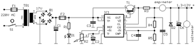
Linear RF Power Meter Circuit Diagram
 
The supply voltage, which can lie between +2.7 V und +5.5 V, is filtered by a 100nF capacitor that diverts residual RF signals to ground. Finally, there is an output capacitor that forms a low-pass filter in combination with the internal circuitry of the LMV225. If this capacitor has a value of 1 nF, the corner frequency of this low-pass filter is approximately 8 kHz. The corner frequency can be calculated using the formula fc = 1 ÷ (2 p COUT Ro) where Ro is the internal output impedance (19.8 k?). The output low-pass filter determines which AM modulation components are passed by the detector.

rf-power-meter-circuit-diagram2
The output, which has a relatively high impedance, provides an output voltage that is proportional to the signal power, with a slope of 40 mV/dB. The output is 2.0 V at 9 dBm and 0.4 V at –40 dBm. A level of 0 dBm corresponds to a power of 1 mW in 50 R. For a sinusoidal wave-form, this is equivalent to an effective voltage of 224 mV. For modulated signals, the relationship between power and voltage is generally different. The table shows several examples of power levels and voltages for sinusoidal signals. The input impedance of the LMV225 detector is around 50 R to provide a good match to the characteristic impedance commonly used in RF circuits.

The data sheet for the LMV225 shows how the 40-dB measurement range can be shifted to a higher power level using a series input resistor. The LMV225 was originally designed for use in mobile telephones, so it comes in a tiny SMD package with dimensions of only around 1 × 1 mm with four solder bumps (similar to a ball-grid array package). The connections are labelled A1, A2, B1 and B1, like the elements of a matrix. The corner next to A1 is bevelled.

Streampowers

Build Intelligent Wire Loop Alarm Circuit With IC

Posted by Unknown 0 comments
Integrated circuit anti-theft alarm system, wire or other lack of a simple circuit. When the lack of wires or cords lacking. MOSFET, it is working or has input voltage at pin G and thus it has a high current flows through the pin D-S that Micro piezo siren was so loud.

Build Intelligent Wire Loop Alarm Circuit With IC

Part List
R1  100K 1/2W 1% Resistor
R2, R4  10K 1/2W 1% Resistor
R3 1  Meg 1/2W 1% Resistor
C1, C3  0.1uF Ceramic Disc Capacitor
C2  0.01uF Ceramic Disc Capacitor
IC1  4001UBE Quad 2-i/p NOR Gate
Q1  MPSA14 Low Power NPN Transistor
SIREN  Micro piezo siren 12V DC 150mA, 110dB @ 1M
LOOP  See “Notes”

The loop can be any type of hookup wire, with a maximum resistance of about 90K. Using very thin wire (40AWG, for example) will make a very sensitive trip wire, but will shorten the distance it can be strung due to the high resistance.

 The siren can be replaced with a relay to drive external load

24V DC Powered Beeper with 4 Separate Inputs

Posted by Unknown Wednesday, August 7, 2013 0 comments
24v DC is a very popular voltage used in industrial settings. This hobby circuit below was designed to accept four different 24v DC alarm input signals, which are then used to drive a single low power beeper. The beeper is a magnetic type with its own oscillator/driver. The four diodes form an “OR” gate so any one of the four inputs will cause the beeper to make noise. A CMOS version of the popular 555 timer is used to strobe the beeper on and off at about 1Hz.


24V DC Powered Beeper with 4 Separate Inputs


Source :Streampowers

1994 Volvo 850 Turbo Change the ECU with A Non Turbo ECU Parts

Posted by Unknown 0 comments


When the ecu of my 1994 Volvo 850 Turbo was showing some bad readings about the knock sensors, I picked and pulled the old ecu and got a new ecu from a 1993 volvo 850 non turbo. Is it possible for an ECU from a turbo car to replace ecu from a non turbo car? Thanks.

Answer: No. The turbo creates a significant change, since the engine compression is changed significantly. 
VVT
A/F Ratio
Wastegate control
Banked injection
Would be different or missing from the ECU. The knock sensor sends signals when the A/F mixture pre-detonates before it can be ignited by the spark plug, and the computer corrects it with VVT. You need to buy the correct ECU.

Dual 3 Way Indoor Outdoor Speaker Set LU43

Posted by Unknown Tuesday, August 6, 2013 0 comments
The DUAL LU43 is petite stylish size, but towering on sound. This 3-way multi-point orator is designed to transport accurate astronomical-fidelity sound apart from of placement. The weather-tough design makes the LU43 ideal intended for undying otherwise temporary open-air avail yourself of. incorporated with the LU43 bring out fix is an amendable logo for vertical before horizontal mounting options. The LU43 is by national absolutely something like anywhere as well as areas ranging from back yards, patios and pool / spa settings.• Frequency Response 100 Hz-20kHz •Woofer 4 edge your way (100mm) polyelite with PVA Surround • Midrange 40mm poly shaft • Tweeter 20mm Piezo field Sensitivity 85.5 dB (2.83v @ 1 measuring device) • Nominal Impedance 4-6 ohms • Power management 50 watts RMS - 100 watts (IPP) creation Dimensions (L x W x H) 5.52 crawl x 5.52 inch x 8.2 inch.


Technical Details

  • Power handling: 50 watts RMS, 100 watts peak
  • 4-Inch polyelite subwoofer with rubber surround sound
  • 40mm polycone midrange and 20mm piezo tweeter
  • Sensitivity; 87dB, Frequency response: 100Hz-20kHz
  • Aluminum grill (non-removable), rotating logo for versatile mounting options, UV treated ABS enclosure
  • 4-inch woofer, 25mm poly cone midrange, and 20mm Piezo dome tweeter
  • 50 watts of RMS power, with 100 watts of peak power
  • Each speaker measures 8.25 x 5.25 x 5.25 inches (HxWxD); 1-year warranty
  • Pair of multipurpose indoor/outdoor speakers in black for permanent or temporary outdoor use
  • Wall-mountable, UV-treated ABS enclosure; mounting brackets included

Wiring Diagrams Application for Any Vehicle

Posted by Unknown 0 comments

Shiftlight does not respond to buttons being pressed. The engine must be running in order to set the pre-shift and shift points on the shiftlight. The unit requires an input signal (tachometer, coil negative, crank angle sensor)if there is no input signal the unit will not respond whenbuttons pressed. MITSUBISHI RVR N23W 4G63 1992 – 97 GM – 2 President G50 VH45DE 1990 – GN – 4 Infinity Q45 G50 VH45DE 1989 – 97.

Pajero V23W 6G72 1991 – GM – 2 N74W 4G64 GM – 3 N73W 4G63 M/T GM – 3 N71W 4G93 N61W 1997 – GM – 3 Cinma III FGY33 VH41DE 1996 – 98 GN – 6 FHY33 VQ30DET GN – 5 Cinma II FGY32 VH41DE 1991 – 96 GN – 4 FPY32 VG30DET 1993 – 96 Cinma I FPY31 VG30DET 1989 – 91 FPY31 VG30DE FPY31 VG30DET 1988 -89 GN – 1 FPY31 VG30DE.

get here

Rj45 Pinout Wiring 10baset 100baset Connection

Posted by Unknown Monday, August 5, 2013 0 comments
Cat5 Wiring on Rj45 Pinout Wiring  How To Make Up A 10baset 100baset Connection  Eia
Rj45 Pinout Wiring How To Make Up A 10baset 100baset Connection Eia.


Cat5 Wiring on Tech Info   Lan Wiring And Pinouts
Tech Info Lan Wiring And Pinouts.


Cat5 Wiring on Quickand Dirty Cat 5 Wiring Howto
Quickand Dirty Cat 5 Wiring Howto.


Cat5 Wiring on Tia Eia 568a   568b Standards For Cat5e Cable
Tia Eia 568a 568b Standards For Cat5e Cable.


Cat5 Wiring on Peak Electronic Design Limited   Ethernet Wiring Diagrams   Patch
Peak Electronic Design Limited Ethernet Wiring Diagrams Patch.


Cat5 Wiring on Terminating Rj 45  Cat5 Cat5e Cat6 Data
Terminating Rj 45 Cat5 Cat5e Cat6 Data.


Cat5 Wiring on Figure A  Standard Eia Tia T568b Wiring Diagram
Figure A Standard Eia Tia T568b Wiring Diagram.


Cat5 Wiring on Cat 5 Wiring
Cat 5 Wiring.


Cat5 Wiring on Networking Guide   Category 5 Wiring Scheme   Straight Through Cable
Networking Guide Category 5 Wiring Scheme Straight Through Cable.


Cat5 Wiring on Cat 5 Wiring
Cat 5 Wiring.