Schematic | Circuit guide | Manual Wiring diagram | Electronic
Showing posts with label simple. Show all posts

Simple Power Pulse Using by LM350 and NE555 Circuit Diagram

Posted by Unknown Friday, December 20, 2013 0 comments
This is a Simple Power Pulse Using by LM350 and NE555 Circuit Diagram. This circuit can use to drive lamp,power LED,DC motor etc. Adjust R5 for output amplitude.Adjust R1 for output power .

Power Pulse Circuit Diagram

Power Pulse Circuit Diagram


The LM350 is adjustable 3-terminal positive voltage regulators is capable of supplying in excess of 3A over a 1.2V to 33V output range.This circuit requires 5-15V power supply.

Simple Lightning Detector

Posted by Unknown Tuesday, December 17, 2013 0 comments
Here is a VLF receiver tuned to 300 kHz designed to detect the crackle of approaching lightning. A bright lamp flashes in sychrony with the lightning bolts indicating the proximity and intensity of the storm. Figure 1 shows the simple receiver which consists of a tuned amplifier driving a modified flasher circuit.

The flasher is biased to not flash until a burst of RF energy, amplified by the 2N3904, is applied to the base of the 2N4403. The receiver standby current is about 350 microamps which is nothing at all to a couple of D cells, hardly denting the shelf life. Of course, the stormier it gets, the shorter the battery life.

Circuit diagram


For best effect, mount the lamp in an old-fashioned holder with an extra-large colored glass lense. Or construct your own fixture with a plate of textured colored glass behind a panel painted with black-crackle paint. Watch a few old science fiction movies for other ideas. A totally different approach is to mount the circuit in an empty glass jar with the antenna and bulb protruding through the top. (A malted-milk jar has a nice, red plastic lid which is easy to work and looks good.) Use a pin jack for the antenna.

The gadget looks quite home-made but fascinating. Boat owners may wish to replace the lamp with a 3-volt beeper to provide an early warning of approaching bad weather. Choose one of those unbreakable clear plastic jars like the large jars of coffee creamer. A little silicone rubber will seal the antenna hole in the lid of the jar. Use a longer antenna for increased sensitivity since there are few electrical noise sources on the lake.

Tune-up is simple: adjust the potentiometer until the regular flashing just stops. (Use a multi-turn trimmer.) When properly adjusted, the lamp will occasionally flash when large motors or appliances switch on and off and an approaching storm will give quite a show. Obviously, tune-up is a bit more difficult during stormy weather. Adjust the pot with no antenna if lightning is nearby. Tune an AM radio to the bottom of the dial to monitor the pulses that the lightning detector is receiving.

This lightning detector is not so sensitive that it will flash with every crackle heard on the radio but will only flash when storms are nearby. Increased sensitivity may be achieved by increasing the antenna length. The experienced experimenter may wish to add another gain stage after the first by duplicating the 2N3904 circuitry including capacitor coupling with the addition of a 47 ohm emitter resistor to reduce the gain somewhat.

This additional gain can cause stability problems if the layout is poor so novices are advised to use a longer antenna or adjust the sensitivity potentiometer more delicately instead! (When operating properly, the additional gain makes the pot adjustment much less critical.)

A Simple NiCd Charger Circuit Diagram

Posted by Unknown Friday, September 27, 2013 0 comments
A simple NiCd charger can be built using ‘junk box’ components and an inexpensive LM317 or 78xx voltage regulator. Using a current limiter composed of R3 and a transistor, it can charge as many cells as desired until a ‘fully charged’ voltage determined by the voltage regulator is reached, and it indicates whether it is charging or has reached the fully charged state. If the storage capacitor (C1) is omitted, pulsed charging takes place. In this mode, a higher charging current can be used, with all of the control characteristics remaining the same.
The operation of the circuit is quite simple. If the cells are not fully charged, a charging current flows freely from the voltage regulator, although it is limited by resistor R3 and transistor T1. The limit is set by the formula Imax ≈ (0.6 V) ÷ R3 For Imax = 200 mA, this yields R3 = 3 Ω. The LED is on if current limiting is active, which also means that the cells are not yet fully charged. The potential on the reference lead of the voltage regulator is raised by approximately 2.9 V due to the voltage across the LED.
Circuit Diagram :
A Simple Nicd Charger Circuit Diagram
This leads to a requirement for a certain minimum number of cells. For an LM317, the voltage between the reference lead and the output is 1.25 V, which means at least three cells must be charged (3 × 1.45 V > 2.9 V + 1.25 V). For a 78xx with a voltage drop of around 3 V (plus 2.9 V), the minimum number is four cells. When the cells are almost fully charged, the current gradually drops, so the current limiter becomes inactive and the LED goes out.
In this state, the voltage on the reference lead of the regulator depends only on voltage divider R1/R2. For a 7805 regulator, the value of R2 is selected such that the current through it is 6 mA. Together with the current through the regulator (around 4 mA), this yields a current of around 10 mA through R1. If the voltage across R1 is 4 V (9 V – 5 V), this yields a value of 390 Ω. The end-of-charge voltage can thus be set to approximately 8.9 V. As the current through the regulator depends on the device manufacturer and the load, the value of R1 must be adjusted as necessary. The value of the storage capacitor must be matched to the selected charging current. As already mentioned, it can also be omitted for pulse charging.
Author: Wolfgang Schmidt   Copyright: Elektor

Simple Portable Amplifier Circuit Diagram

Posted by Unknown Thursday, August 15, 2013 0 comments
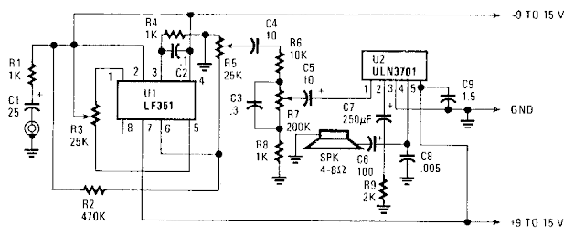
Simple Portable Amplifier Circuit Diagram Ul, an FET op amp needs a bipolar voltage atpins 4 and 7 with a common ground for optimum gain. You can calculate the gain by dividing R2 by Rl. Zero-set balance can be had through pins i and 5 through R3. Put a voltmeter between pin 6 and ground and adjust R3 for zero voltage. Once you`ve established that, you can measure the ohmic resistance at each side of R3`s center tap and replace the potentiometer with fixed resistors. R6, R7, RS,and C3 forrn a tone control that will give you added bass boost, if needed

Simple Portable Amplifier Circuit Diagram


Simple Portable Amplifier Circuit Diagram

Simple ON OFF Touch Switch with 555 Schematic

Posted by Unknown Sunday, August 11, 2013 0 comments
This simple ON OFF touch switch circuit is based on the well known timer IC 555 (IC1), which drives a relay that acts like a switch. The metal surfaces can have what form we want, but it should be clean and very close to the circuit.

Touch plate MP1 in order to close the contact of relay RL1 [ON], or plate MP2 in order to open the contact of RL1 [OFF]. The Led D2 turns on when the contacts of RL1 are closed. Two small pieces of metal can be used as sensor plates.

555 ON/OFF Touch Switch Schematic

Simple ON OFF Touch Switch with 555 Schematic

Parts List
R1 = R2 = 3.3M
R3 = 10K
R4 = 1K
C1 = 10nF
D1 = 1N4007
Q1 = BC547
IC = NE555
12V relay

Simple Regulator Loss Cutter Circuit Diagram

Posted by Unknown Friday, August 9, 2013 0 comments
This is Simple Regulator Loss Cutter Circuit Diagram . Large input-to-output voltage differentials, caused by wide input voltage variations, reduce a linear regulator`s efficiency and increase its power dissipation. A switching preregulator can reduce this power dissipation by minimizing the voltage drop across an adjustable linear regulator to a constant 1.5-V value. The circuit operates the LT1084 at slightly above its dropout voltage. To minimize power dissipation, a low-dropout linear regulator was chosen. The LT1084 functions as a conventional adjustable linear regulator with an output voltage that can be varied from 1.25 to 30 V. 

 Regulator Loss Cutter Circuit Diagram


Regulator Loss Cutter Circuit Diagram

Simple Phone Tap Circuit

Posted by Unknown Wednesday, June 12, 2013 0 comments

This circuit is extremely simple, therefore there is less chance of any problems. It can be placed anywhere on the phone line and it will record any conversation on any phone on that line.
   
Part                         Total Qty.              Description

R1                            1                    470 Ohm 1/4 Watt Resistor   
R2                            1                    1K 1/4 Watt Resistor   
R3                            1                     100K 1/4 Watt Resistor   
R4                            1                    6K 1/4 Watt Resistor   
C1, C2                     2                    0.01 uF 100V Ceramic Capacitor   
K1                            1                    24VDC Reed Relay   
MISC                       1                    Wire, Headphone Plugs, Phone Plug Or Alligator Clips   

Electronics Circuit Application

Please note: I have received several emails saying that this circuit will not work and that it may hold your line off hook and to me it looks like it will (it would put quite a load on the phone line). For some, it has worked fine. Build at your own risk.

Simple servo controller Schematic

Posted by Unknown Wednesday, May 29, 2013 0 comments
This cicuit allows you to test a servo. The angle of the servo can be set by means of the 10k potmeter. Perhaps you will not be able to reach all positions with this circuit. Playing with other resistors may help.


Part component;

1 555 timer IC
1 BC547 transistor
1 10k Ohm potentiometer
2 10k Ohm resistors
2 100nF condensators
1 220k Ohm resistor
1 15k Ohm resistor

Simple Flashing Lights Schematic

Posted by Unknown Friday, April 26, 2013 0 comments
This is a straightforward flashing milds circuit can be used as beacon. The meeting consists basically of two blinking steps that commands two mild bulbs. With the lend a hand of P1 that you might be ready to adjust the flashing frequency between some restricts. There are 2 phases for the circuit, the 2d works the comparable manner as the opposite but with the lend a hand of a wire bridge or a switch that you could select different working modes.A bridge between M and three means: 2 unbiased blinks.

Circuit diagram :
Flashing Lights Schematic-Circuit Diagram

Flashing Lights Schematic Circuit Diagram

If there is a bridge between M and 2, then the lamps gentles alternatively with a frequency that can be modifyed with P1. And at last there may just be one extra possibility for M and 1, where the lamps blinks at the related time. The flashing milds circuit works with voltages between 3V and 15V. The lamps voltage have to be 2/3 of working voltage. R5 and R10 are chosen so that the lamps are about to light.

Simple Purpose Alarm

Posted by Unknown Sunday, April 21, 2013 0 comments
The alarm may be used for a variety of applications, such as frost monitor, room temperature monitor, and so on. In the quiescent state, the circuit draws a current of only a few microamperes, so that, in theory at least, a 9 V dry battery (PP3, 6AM6, MN1604, 6LR61) should last for up to ten years. Such a tiny current is not possible when ICs are used, and the circuit is therefore a discrete design. Every four seconds a measuring bridge, which actuates a Schmitt trigger, is switched on for 150 ms by a clock generator. In that period of 150 ms, the resistance of an NTC thermistor, R11, is compared with that of a fixed resistor. If the former is less than the latter, the alarm is set off.

When the circuit is switched on, capacitor C1 is not charged and transistors T1–T3 are off. After switch-on, C1 is charged gradually via R1, R7, and R8, until the base voltage of T1 exceeds the threshold bias. Transistor T1 then comes on and causes T2 and T3 to conduct also. Thereupon, C1 is charged via current source T1-T2-D1, until the current from the source becomes smaller than that flowing through R3 and T3 (about 3 µA). This results in T1 switching off, so that, owing to the coupling with C1, the entire circuit is disabled. Capacitor C1 is (almost) fully charged, so that the anode potential of D1 drops well below 0 V. Only when C1 is charged again can a new cycle begin.


It is obvious that the larger part of the current is used for charging C1. Gate IC1a functions as impedance inverter and feedback stage, and regularly switches on measurement bridge R9–R12-C2-P1 briefly. The bridge is terminated in a differential amplifier, which, in spite of the tiny current (and the consequent small transconductance of the transistors) provides a large amplification and, therefore, a high sensitivity. Resistors R13 and R15 provide through a kind of hysteresis a Schmitt trigger input for the differential amplifier, which results in unambiguous and fast measurement results. Capacitor C2 compensates for the capacitive effect of long cables between sensor and circuit and so prevents false alarms.

If the sensor (R11) is built in the same enclosure as the remainder of the circuit (as, for instance, in a room temperature monitor), C2 and R13 may be omitted. In that case,C3 willabsorb any interference signals and so prevent false alarms. To prevent any residual charge in C3 causing a false alarm when the bridge is in equilibrium, the capacitor is discharged rapidly via D2 when this happens. Gates IC1c and IC1d form an oscillator to drive the buzzer (an a.c. type). Owing to the very high impedance of the clock, an epoxy resin (not pertinax) board must be used for building the alarm. For the same reason, C1 should be a type with very low leakage current. If operation of the alarm is required when the resistance of R11 is higher than that of the fixed resistor, reverse the connections of the elements of the bridge and thus effectively the inverting and non-inverting inputs of the differential amplifier.

An NTC thermistor such as R11 has a resistance at –18 °C that is about ten times as high as that at room temperature. It is, therefore, advisable, if not a must, when precise operation is required, to consult the data sheet of the device or take a number of test readings. For the present circuit, the resistance at –18 °C must be 300–400 kΩ. The value of R12 should be the same. Preset P1 provides fine adjustment of the response threshold. Note that although the prototype uses an NTC thermistor, a different kind of sensor may also be used, provided its electrical specification is known and suits the present circuit.


Author: K. Syttkus
Copyright: Elektor Electronics


Simple Lighting Surge Protector Circuit

Posted by Unknown Thursday, April 11, 2013 0 comments
GDT’s are special type of gas filled tubes used for wide range of electronic/electrical circuits for providing protection against lightning and other power surges.  These tubes basically has two electrodes that are kept inside a gas filled closed envelope. In case of electronic applications, the container is mostly ceramic in nature. For high grade electrical applications military tubes are used. The electrical characteristics of this tubes depends on the pressure and composition of gas, and the distance between the two electrodes contained inside. The most commonly used gases in GDT’s are given below.

1) Hydrogen gases
2) Deuterium gases
3) Noble gases
4) Elemental vapors (metals and nonmetals)
5) Other gases
6) Insulating gases
An image of a ceramic discharge tube is shown below. Take a look.

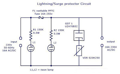
There will be conduction inside the GDT’s due to ionization of gas molecules. Each GDT have a specific voltage and current rating. A simple lightning protector circuit is given below.

Lighting/Surge Protector Circuit

In power lines, usually large amount of voltage is induced (typically very short time with high amplitude) due to lightning (direct or indirect strike) or Transients*
* (Transients caused by other equipments are usually caused by the discharge of stored energy in inductive and capacitive components. Electric motors, such as those used in elevators, heating, air conditioning, refrigeration or other inductive loads, can create a continuous stream of 250V to 1000V transients. DC motor drives, variable speed AC motor drives, DC power supply switching, and portable power tools are other sources of transients.)

Lightning protection circuit:

Simple Lighting Surge Protector Circuit

The basic surge suppression circuit shown below consists of a VDR** (Voltage Dependent Resistor) and gas surge suppressor (GDT) connected in series. The protection circuit is connected between live and mains lead. Normally no current flows through GDT and VDR1. When   the voltage between the terminals is higher than the sum of voltage ratings of GDT and VDR1 (here both GDT UZ470B and VDR S20K250 has 250v 16A rating), current starts to flow through those components. 

If more the voltage rises then more current starts to flow through GDT and VDR1.When the current is normal, the circuit is reset and resumes it’s functioning. Thus the current cannot be raised much over that predetermined value. When the voltage again goes back to normal values G1 and VDR1, the conducting stops and the circuit remains normal.  If the flowing current is more than the specified value of main self-resettable fuse, the fuse will break and the circuit will be protected. After the current is normal, the fuses resets and continue its functioning (protection against short circuit and overload). 

The circuit is designed to protect sensitive electronic devices against overvoltage transients in normal mains voltage and overload/ short circuit. Two neon pilot lamps are also provided with the circuit diagram to show the status of input and load supply.

(**A VDR (Voltage Dependent Resistor) is an electronic component with a “diode-like” nonlinear current–voltage characteristic. The name is a portmanteau of variable resistor.  VDRs are often used to protect circuits against excessive transient voltages by incorporating them into the circuit in such a way that, when triggered, they will shunt the current created by the high voltage away from the sensitive components. A VDR is also known as Voltage Dependent Resistor or VDR. A VDR’s function is to conduct significantly increased current when voltage is excessive.)

Voltage Dependent Resistor

Advantages:

1)      Normal working voltage = 230v AC/DC
2)      Maximum current rating=16A
3)      Cut-off current =16A
4)      Cut-off voltage= >300v R.M.S
5)      Protection against overloads
6)      Protection for short circuit

Applications:

1)      Protection for sensitive components
2)      Protection for motor devices
3)      Telephone line protection
4)      SMPS protection

Simple Clap Operated Stairway Light Switch Circuit

Posted by Unknown Wednesday, April 10, 2013 0 comments
Stairways, corridors or small indoor passages often tend to be dark throughout the day irrespective of the outdoor ambient light conditions. Therefore keeping such passages illuminated all the the time becomes imperative, however this leads to unnecessary wastage of electricity.

 An innovative way of solving this problem has been discussed in this article, by employing a clap operated momentary light switch circuit.

The circuit diagram may be understood as follows:

The idea is to switch ON the connected lights in the corridor through a  clap sound, whenever the involved passage is utilized.
The clap sound triggers the circuit and keeps the connected lights switched ON for a few seconds or until the predetermined time is lapsed, after which the lights are automatically switched OFF.

The configuration is actually a transistor based clap switch, but without a flip flop stage, rather the flip flop is replaced by a delay OFF timer stage for the necessary switching and sustaining of the lights for a fixed predetermined period.
The stage as usual includes a sound sensor stage consisting of a mic and the subsequent transistor amplifier stage using a couple BC547 transistors.

The next stage consists of the PNP transistor BC557 which receives the signals amplified from the first stage via the 47uF capacitor.
The fed signals are further amplified to much greater levels for triggering the final LED driver stage.
The LED driver stage consists of a group of white LEDs which provides enough light for illuminating a small passage premise.
The two 39K resistors and the 220uF capacitors form the basic delay OFF timer and decides for how many seconds the driver stage remains ON with the LEDs lit.

The power to the circuit can be either applied by incorporating a standard transformer/bridge AC/DC adapter or if the circuit needs to be more compact, a transformerless power supply may be included with the below shown circuit.

All the NPN transistors are BC547B and the single PNP transistor is a BC557B, LEDs are ordinary 5mm high efficiency white LEDs.

The coil can be of any type, a 100mH choke will also do, its introduced in order to keep the circuit stable and for avoiding self oscillations.


Simple Touch Switch

Posted by Unknown Monday, April 8, 2013 0 comments


This is a simple touch circuit diagram.I think you can use this for
many purposes.I have used this circuit as a security circuit
device.Here I have used very common Transistors   2N 5458 N and 2N2222
to gain the signal .2N3906 Transistor work as a switch here.


Note 
# Build this circuit on a PCB
# Use a copper plate to touch senseer 
# Dont supply more than12V

Simple LED flasher circuit using NE555 timer IC

Posted by Unknown Friday, April 5, 2013 0 comments
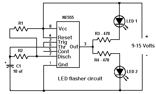
This circuit consumes more power, but its advantage is when you need a variable flash rate, like for strobe circuits. You can actually use this circuit as a remote control for strobes that have a remote input. Of course, it has many other applications besides strobes.

Simple LED flasher circuit using NE555 timer ICLED flasher circuit
  • R1, R2, C1 and the supply voltage determine the flash rate. Using a regulated power supply will do much to insure a stable flash rate. For a variable flash rate, replace R1 with a 1 megohm pot in series with a 22k resistor.
  • The duty cycle of the circuit (the percentage of the time LED 1 is on to the time it is off during each cycle) is deterimed by the ratio of R1 to R2. If the value of R1 is low in relationship to R2, the duty cycle will be near 50 percent. If you use both LEDs, you will probably want a 50 percent duty cycle. On the other hand, if R2 is low compared to R1, the duty cycle will be less than 50 percent. This is useful to conserve battery life, or to produce a strobe type effect, when only LED1 is used.
  • The NE555 timer chip can be damaged by reverse polarity voltage being applied to it. You can make the circuit goof proof by placing a diode in series with one of the supply leads.
  • The purpose of R3 and R4 is to limit current through the LEDs to the maximum they can handle (usually 20 milliamps). You should select the value of these according to the supply voltage. 470 ohms works well with a supply voltage of 9-12 volts. You will need to reduce the value for lower supply voltages.
  • Rainbow Kits offers several kits to build the above circuit. You can also order these kits from RadioShack.com. The Radio Shack catalog numbers (and web pages) are as follows: standard kit with two 5mm red LEDs, (990-0067), kit with two red, two green and two yellow 3mm LEDs, (990-0063), kit with jumbo green LEDs, (990-0048), kit with jumbo red LEDs, (990-0049). You can also buy all the parts to build the circuit at your local Radio Shack store, including a circuit board (276-159B).
I have built a miniature strobe circuit as follows. Use a 250k pot in series with a 4.7k resistor for R1. The 4.7k resistor sets the upper flash rate limit. Use 2.2k for R2. That sets a really short duty cycle. For this circuit, you dont use LED 2 or R4. For LED 1, I used a two Radio Shack white LEDs in series and no R-3. The circuit runs on a 9 v battery.  link