Schematic | Circuit guide | Manual Wiring diagram | Electronic
Showing posts with label portable. Show all posts

Mini Portable Guitar Amplifier

Posted by Unknown Thursday, October 3, 2013 0 comments

Can be fitted into a packet of cigarettes, Also suitable as Fuzz-box

This small amplifier was intended to be used in conjunction with an electric guitar to do some low power monitoring, mainly for practice, either via an incorporated small loudspeaker or headphones. The complete circuit, loudspeaker, batteries, input and output jacks can be encased in a small box having the dimensions of a packet of cigarettes, or it could be fitted also into a real packet of cigarettes like some ready-made units available on the market.
This design can be used in three different ways:

  • Loudspeaker amplifier: when powered by a 9V alkaline battery it can deliver about 1.5W peak output power to the incorporated loudspeaker.
  • Headphone amplifier or low power loudspeaker amplifier: when powered by a 3V battery (2x1.5V cells) it can drive any headphone set type at a satisfactory output power level or deliver to the incorporated loudspeaker about 60mW of output power. This configuration is useful for saving battery costs.
  • Fuzz-box: when powered by a 3V battery (2x1.5V cells) and having its output connected to a guitar amplifier input the circuit will behave as a good Fuzz-box, showing an output square wave with marked rounded corners, typical of valve-circuits output when driven into saturation.

Circuit diagram:

Mini Portable Guitar Amplifier

Mini Guitar Amplifier Circuit Diagram

Parts:

R1__________22K 1/4W Resistor
C1__________10µF 25V Electrolytic Capacitor
C2__________100nF 63V Polyester or Ceramic Capacitor
C3__________220µF 25V Electrolytic Capacitor
IC1_________TDA7052 Audio power amplifier IC
J1,J2_______6.3mm Stereo Jack sockets (switched)
SPKR_______8 Ohm Loudspeaker (See Notes)
B1_________9V PP3 Battery or 3V Battery (2 x 1.5V AA, AAA Cells in series etc.)
Clip for PP3 Battery or socket for 2 x 1.5V AA or AAA Cells

Notes:

  • For the sake of simplicity and compactness, this unit employs a dual bridge IC amplifier and a few other parts. For the same reason no volume or tone controls are provided as it is supposed that the controls already existing on the electric guitar will serve satisfactorily to the purpose.
  • No power switch is used: the battery voltage will be applied to the circuit when the input plug will be inserted in the input jack socket J1. For this purpose be sure that the input plug is a common 1/4 inch guitar mono jack plug and J1 is a 1/4 inch stereo jack socket.
  • The output jack socket J2 must be a switched stereo type. The changeover switching is arranged in such a way that, when a common headphones stereo jack plug is inserted into the socket, the loudspeaker will be disabled and the mono output signal will drive both the headsets in series, allowing full headphone reproduction. When used as a Fuzz-box output, a mono jack plug must be inserted into J2.
  • If the amplifier is intended to be encased in a packet of cigarettes, standard loudspeaker diameter should be 57 or 50mm.

Technical data:

Max output power: 1.5W @ 9V supply - 8 Ohm load; 60mW @ 3V supply - 8 Ohm load
Frequency response: Flat from 20Hz to 20kHz
Total harmonic distortion @ 100mW output: 0.2%
Max input voltage @ 3V supply: 8mV RMS
Minimum input voltage for Fuzz-box operation: 18mV RMS @ 3V supply
Current consumption @ 400mW and 9V supply: 200mA
Current consumption @ 250mW and 9V supply: 150mA
Current consumption @ 60mW and 3V supply: 80mA
Quiescent current consumption: 6mA @ 9V, 4mA @ 3V supply
Fuzz-box current consumption: 3mA @ 3V supply

Copyright: www.redcircuits.com

Mini Portable Guitar Amplifier

Posted by Unknown Wednesday, October 2, 2013 0 comments

Can be fitted into a packet of cigarettes Also suitable as Fuzz-box

This small amplifier was intended to be used in conjunction with an electric guitar to do some low power monitoring, mainly for practice, either via an incorporated small loudspeaker or headphones.

The complete circuit, loudspeaker, batteries, input and output jacks can be encased in a small box having the dimensions of a packet of cigarettes, or it could be fitted also into a real packet of cigarettes like some ready-made units available on the market.

Circuit diagram:

MiniGuitarAmp Mini Portable Guitar Amplifier Circuit Diagram

Parts Description
R1 22K 1/4W Resistor
C1 10µF 25V Electrolytic Capacitor
C2 100nF 63V Polyester or Ceramic Capacitor
C3 220µF 25V Electrolytic Capacito
IC1 TDA7052 Audio power amplifier IC
J1,J2 6.3mm Stereo Jack sockets (switched)
SPKR 8 Ohm Loudspeaker (See Notes)
B1 9V PP3 Battery or 3V Battery (2 x 1.5V AA, AAA Cells in series etc.)
Clip for PP3 Battery or socket for 2 x 1.5V AA or AAA Cells

This design can be used in three different ways:

  • Loudspeaker amplifier: when powered by a 9V alkaline battery it can deliver about 1.5W peak output power to the incorporated loudspeaker.
  • Headphone amplifier or low power loudspeaker amplifier: when powered by a 3V battery (2x1.5V cells) it can drive any headphone set type at a satisfactory output power level or deliver to the incorporated loudspeaker about 60mW of output power. This configuration is useful for saving battery costs.
  • Fuzz-box: when powered by a 3V battery (2x1.5V cells) and having its output connected to a guitar amplifier input the circuit will behave as a good Fuzz-box, showing an output square wave with marked rounded corners, typical of valve-circuits output when driven into saturation.

Notes:

  • For the sake of simplicity and compactness, this unit employs a dual bridge IC amplifier and a few other parts. For the same reason no volume or tone controls are provided as it is supposed that the controls already existing on the electric guitar will serve satisfactorily to the purpose.
  • No power switch is used: the battery voltage will be applied to the circuit when the input plug will be inserted in the input jack socket J1. For this purpose be sure that the input plug is a common 1/4 inch guitar mono jack plug and J1 is a 1/4 inch stereo jack socket.
  • The output jack socket J2 must be a switched stereo type. The changeover switching is arranged in such a way that, when a common headphones stereo jack plug is inserted into the socket, the loudspeaker will be disabled and the mono output signal will drive both the headsets in series, allowing full headphone reproduction. When used as a Fuzz-box output, a mono jack plug must be inserted into J2.
  • If the amplifier is intended to be encased in a packet of cigarettes, standard loudspeaker diameter should be 57 or 50mm.

Source:www.redcircuits.com

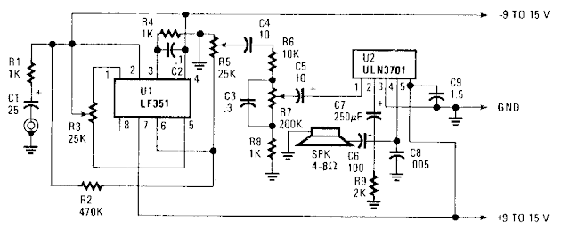
Simple Portable Amplifier Circuit Diagram

Posted by Unknown Thursday, August 15, 2013 0 comments
Simple Portable Amplifier Circuit Diagram Ul, an FET op amp needs a bipolar voltage atpins 4 and 7 with a common ground for optimum gain. You can calculate the gain by dividing R2 by Rl. Zero-set balance can be had through pins i and 5 through R3. Put a voltmeter between pin 6 and ground and adjust R3 for zero voltage. Once you`ve established that, you can measure the ohmic resistance at each side of R3`s center tap and replace the potentiometer with fixed resistors. R6, R7, RS,and C3 forrn a tone control that will give you added bass boost, if needed

Simple Portable Amplifier Circuit Diagram


Simple Portable Amplifier Circuit Diagram