Schematic | Circuit guide | Manual Wiring diagram | Electronic
Showing posts with label light. Show all posts

LED Brake Rear Light Specifically for motorcycles Circuit diagram

Posted by Unknown Tuesday, October 1, 2013 0 comments
LEDs are used more and more in motor vehicles, replacing the standard incandescent lamps because they are more energy efficient and have a much longer life expectancy. In this article we describe a simple LED tail light that has been specifically designed for motorcycles, scooters and mopeds. There appears to be a significant need among motorcyclists for rear lights with LEDs, as evidenced by the many messages on this topic that turn up in various internet forums. The circuits that accompany these messages are often very rudimentary and therefore not very robust.

Mini project:


When designing an LED light for a motorcycle the following criteria need to be considered:

• Large variations of on-board voltage, this has a significant influence on light intensity.
• The circuit has to be (mechanically) robust.
• High light output is required (visibility = safety).
• Clearly visible difference in light intensity between rear light and brake light function.

After reading some of the literature concerning the use of LEDs in motor vehicles, it appears that the most common reason why LEDs still fail is the incorrect and/or insufficient use of series resistors.
In poorly implemented circuits there are often a number of LEDs connected in parallel which are all fed from a single series resistor. Because of small variations between LEDs, one LED can quickly give up the ghost. This causes an increase in current through the remaining LEDs and can easily lead to a domino effect, ultimately resulting in the failure of the entire circuit.With high-intensity LEDs, a small variation in current is immediately obvious as a large variation in light output.

This has to be taken into account when designing a circuit. This is important because when the engine rev speed goes up, the on-board voltage increases significantly. It would appear that you were braking when you actually opened the throttle instead.LEDs need mainly a constant current.That is why most circuits choose to drive LEDs from a constant-current source.

Circuit

This circuit has been designed to operate both as a motorcycle rear light and as a brake light. This requires two different currents. Because the voltages measured on the author’s motorcycle varied from 10.5 to 15 V and because two different currents are required for the total of 17 high-intensity LEDs it was not possible to use only one constant-current source.

Circuit diagram:

The idea was to turn the strongly varying DC voltage into a nice constant voltage first and then turn that into a constant current through a number of series resistors. The problem that is highlighted in many forums is the fact that the signal for the brake light is a positive voltage. It would require a lot of work on the motorcycle to change this. That is why the decision was made for a de sign that regulates the voltage on the chassis side, with the aid of a negative voltage regulator, a 7908. The disadvantage of this arrangement is that an additional chassis wire is required; normally the minus side of the lamps is directly connected to the chassis of the motorcycle.

However, the advantage is that both the + from the rear light as well as the + from the brake light can be directly connected to the LEDs.The ‘lamp’ con sists of a centre part with nine round, red,5-mm LEDs (HLMP EG08 Y200) wi th positioned around that eight oval ,r e d L E D s HLMP AD61 of 5 mm.The round LEDs D12 through D20 which have qui te a narrow radi ation angle are connected in series in sets of 3. Three of the se ‘strings’ are connected in parallel and each string has its own series resistor.

The oval LEDs D4 to D11 which have a wide radiation pattern are connected with two in series, so there are therefore four strings connected in parallel. These ensure with their wide radiation angle of 110 degrees that the rear/brake-light is also clearly visible from the side.The oval and round strings are connected to the brake contact via diodes. When the brake is operated all the strings are presented with the +12V from the battery via the series resistors. The light intensity therefore depends on the current that flows as a result of the series resistor (and the voltage drop across the diodes).

When the brake is not operated, the LEDs strings are still connected to the positive voltage of the battery, but this time via additional resistors R1 and R2.Because of the value of these resistors,the current is much lower and therefore also the light intensity. The intensity of the brake light can be adjusted using the series resistors (R3 to R9) in each of the individual strings,the brightness of the rear light is selected with the additional series resistors R1 and R2.Diode D1 has been added to protect the circuit from reverse connection of the power supply voltage.Electrolytic capacitors finally provide filtering for the fairly large varying,and not so clean, voltage.

The circuit was built into a silver coloured tube by the author. The electronics are mounted on two pieces of prototyping board, one behind the other,in the tube. The front (visible) PCB holds the LEDs and the series resistors. The LEDs are arranged as indicated next to the schematic. The 9 round LEDs are mounted in the middle of the rear light in a square pattern. The oval LEDs are mounted in a circle around the square.

The second PCB contains the remaining parts and the regulator.You can modify the circuit to your heart’s content by adding more strings, each fitted with its own diode and two resistors (a series resistor such as R3) and a resistor to +12 V (such as R1).The total current (when braking), must not exceed the maximum rating of the voltage regulator, this amounts to 1 A.

Author : Marcel Ulrich Copyright : elektor

Trailer Light Wiring Diagram Advanced Images Search Engine

Posted by Unknown Friday, August 16, 2013 0 comments
Trailer Wiring Diagrams on Trailer Light Wiring Diagram Advanced Images Search Engine
Trailer Light Wiring Diagram Advanced Images Search Engine.


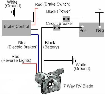
Trailer Wiring Diagrams on How To Install A Trailer Brake Controller On A Tow Vehicle
How To Install A Trailer Brake Controller On A Tow Vehicle.


Trailer Wiring Diagrams on More Information About All New C K Trailer Tow Wiring Diagram Here
More Information About All New C K Trailer Tow Wiring Diagram Here.


Trailer Wiring Diagrams on There Here Is The Wiring Diagram For The Trailer Wiring For Your Truck
There Here Is The Wiring Diagram For The Trailer Wiring For Your Truck.


Trailer Wiring Diagrams on Trailer Wiring Electrical Connections Are Used On Car  Boat And
Trailer Wiring Electrical Connections Are Used On Car Boat And.


Trailer Wiring Diagrams on Wiring Diagrams For Information On How To Hook Up Your Vehicle To The
Wiring Diagrams For Information On How To Hook Up Your Vehicle To The.


Trailer Wiring Diagrams on Knoxville Trailer Sales  Pace  Hank  Leonard  Millennium  Dandy Dump
Knoxville Trailer Sales Pace Hank Leonard Millennium Dandy Dump.


Trailer Wiring Diagrams on Travel Trailer Wiring Diagram Advanced Images Search Engine
Travel Trailer Wiring Diagram Advanced Images Search Engine.


Trailer Wiring Diagrams on Don   T You Just Hate When You Spend Hours Rewiring A Trailer Only To
Don T You Just Hate When You Spend Hours Rewiring A Trailer Only To.


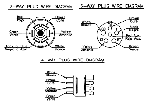
Trailer Wiring Diagrams on Trailer Wiring Diagram Trailer Plug Diagram
Trailer Wiring Diagram Trailer Plug Diagram.


Light dimmer circuit AC 120W

Posted by Unknown Wednesday, May 29, 2013 0 comments
This is Ac light dimmer circuit diagram.You can use bulbs up to 120W.Here You can use common VR.Triac should have heat sink.


Note
# Dont pass 120W.
# This is not good for kids because this is 230Ac circuit.

Light Aircraft Association

Posted by Unknown Monday, May 27, 2013 0 comments
Light Aircraft on Icon A5     Amphibian Special Light Sport Aircraft  S Lsa
Icon A5 Amphibian Special Light Sport Aircraft S Lsa.


Light Aircraft on Welcome To The Light Aircraft Association
Welcome To The Light Aircraft Association.


Light Aircraft on Light Aircraft Corp
Light Aircraft Corp.


Light Aircraft on And Astronautics University And The Nanjing Light Aircraft Co Ltd
And Astronautics University And The Nanjing Light Aircraft Co Ltd.


Light Aircraft on What Kinds Of Ultralight Aircraft
What Kinds Of Ultralight Aircraft.


Light Aircraft on Vampire Light Sport Aircraft    Haute Jets
Vampire Light Sport Aircraft Haute Jets.


Light Aircraft on Aircraft Lights  Grimes  Honeywell   Aerosup
Aircraft Lights Grimes Honeywell Aerosup.


Light Aircraft on Fanwing  First Personal Aircraft Propelled By Fans   Futuristic News
Fanwing First Personal Aircraft Propelled By Fans Futuristic News.


Light Aircraft on To Develop And Sell The Innovative E Go Light Aircraft
To Develop And Sell The Innovative E Go Light Aircraft.


Light Aircraft on Aircraft Computer Mouse With Led Lights   Geekalerts
Aircraft Computer Mouse With Led Lights Geekalerts.


Simple Clap Operated Stairway Light Switch Circuit

Posted by Unknown Wednesday, April 10, 2013 0 comments
Stairways, corridors or small indoor passages often tend to be dark throughout the day irrespective of the outdoor ambient light conditions. Therefore keeping such passages illuminated all the the time becomes imperative, however this leads to unnecessary wastage of electricity.

 An innovative way of solving this problem has been discussed in this article, by employing a clap operated momentary light switch circuit.

The circuit diagram may be understood as follows:

The idea is to switch ON the connected lights in the corridor through a  clap sound, whenever the involved passage is utilized.
The clap sound triggers the circuit and keeps the connected lights switched ON for a few seconds or until the predetermined time is lapsed, after which the lights are automatically switched OFF.

The configuration is actually a transistor based clap switch, but without a flip flop stage, rather the flip flop is replaced by a delay OFF timer stage for the necessary switching and sustaining of the lights for a fixed predetermined period.
The stage as usual includes a sound sensor stage consisting of a mic and the subsequent transistor amplifier stage using a couple BC547 transistors.

The next stage consists of the PNP transistor BC557 which receives the signals amplified from the first stage via the 47uF capacitor.
The fed signals are further amplified to much greater levels for triggering the final LED driver stage.
The LED driver stage consists of a group of white LEDs which provides enough light for illuminating a small passage premise.
The two 39K resistors and the 220uF capacitors form the basic delay OFF timer and decides for how many seconds the driver stage remains ON with the LEDs lit.

The power to the circuit can be either applied by incorporating a standard transformer/bridge AC/DC adapter or if the circuit needs to be more compact, a transformerless power supply may be included with the below shown circuit.

All the NPN transistors are BC547B and the single PNP transistor is a BC557B, LEDs are ordinary 5mm high efficiency white LEDs.

The coil can be of any type, a 100mH choke will also do, its introduced in order to keep the circuit stable and for avoiding self oscillations.


Traffic Light Controller

Posted by Unknown 0 comments
Here the simple traffic light controller which is could be used to educate kids rudiments of traffic light guidelines. The circuit utilizes easily available electronic parts. It generally consists of rectifier diodes (1N4001), a 5V regulator 7805, two timers circuit using IC 555, two relays (5V, single-changeover), three 15W, 230V light bulbs and also several discrete parts.

Traffic Light Controller Circuit diagram :


Mains electrical power is stepped down by transformer X1 to provide a secondary output voltage of 9V, 300 mA – AC. Then the transformer output current is rectified by a full-wave bridge rectifier composed of diodes D1 through D4, filtered by capacitor C1 and also regulated by IC 7805 (IC1).

IC2 is wired as a multivibrator with ‘on’ and ‘off’ periods of about 30 seconds each with the part values determined. Once mains power switch is turned on, pin 3 of IC2 goes high for 30 seconds. This, in turn, energises relay RL1 via transistor T1 and the red bulb (B1) glows through its normally-open (N/O) contact. At the same time, mains power is turned off from the pole of relay RL2. As the ‘on’ time of IC2 ends, a triggers IC3 through C5. IC3 is set up as a monostable with ‘on’ time of about 4 seconds, which indicates pin 3 of IC3 will stay high for this period of time and energise relay RL2 through driver transistor T2. The amber bulb (B2) thus lightings up for 4 seconds.

Immediately after 4-second time period of timer IC3 at pin 3 lapses, relay RL2 de-energises and also the green bulb (B3) lights up for the rest of ‘off’ period of IC2, which is about 26 seconds. The green bulb is turned on through the normally closed (N/C) contacts of relay RL2. So when mains electrical switch is turned on, red light will light up for 30 seconds, amber for 4 seconds and green for 26 seconds.

You can easily build this circuit on a general purpose PCB and enclose in a protected box. The box needs to have sufficient area for installing transformer X1 and also two relays. It could be installed near 230V AC, 50Hz power supply or mounted on the PVC tube applied in assembly of the traffic light box.

Design of the traffic light container box is demonstrated in following image:


A stout cardboard box of 30x15x10cm3 is needed for housing the lights. To make certain durability, work with a 10x45cm2 plywood plate having 1.5 centimeters thickness and also secure onto it three light outlets and the box utilizing nuts and bolts or screws. Make three tubes of thin aluminium sheet, which is easily offered in equipment stores. The inner diameter of aluminium tubes ought to be such that these can well match on the light outlets. Working with a sharp knife, make holes opposite the outlets carefully. Wire the outlets at the back and take the cables out through the PVC tube.

To begin with, fix three 15W light bulbs (B1 through B3) and then press on the tubes. Support the other ends of the tubes in the holes made on the front panel of cardboard box. Sandwich gelatine papers of the three colors in between two sheets of cardboard and fix over the tubes. The visibility of red, amber and also green lights enhances with their installation on the tubular shape.