Schematic | Circuit guide | Manual Wiring diagram | Electronic
Showing posts with label 5. Show all posts

Circuit design tutorial in CircuitMaker 5

Posted by Unknown Thursday, December 26, 2013 0 comments
In this tutorial we are going to learn how to design and simulate a circuit schematic in CircuitMaker 5. For example we are going to design a 12V to 5V  dc-dc converter circuit diagram.  This is the circuit below that we are going to design. 

Fig-1: 12V to 5V  dc-dc converter circuit diagram


Let’s start design the circuit in circuitmaker 5.


Step-1: Open a new document.
Go to “File>New” as shown below or simply press “CTRL+N” 


This will opened a new workspace named as "UNTITLED.CKT(1)".As shown below...


Step-2: Device Selection.

Click on  “Parts”-(Use to display and select device) tool icon form tool bar. See below…

Or, simply hit on “x” from keyboard.This will bring up  “Device Selection” window.From this window select a 12V DC voltage soure by “Sources>Linear>V source” and change the voltage 10V to 12V as shown below.


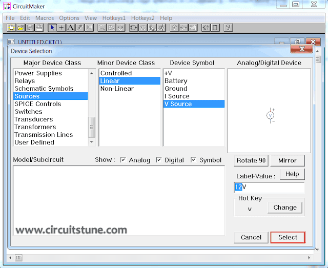
After that click on “Select” or press “Enter”.

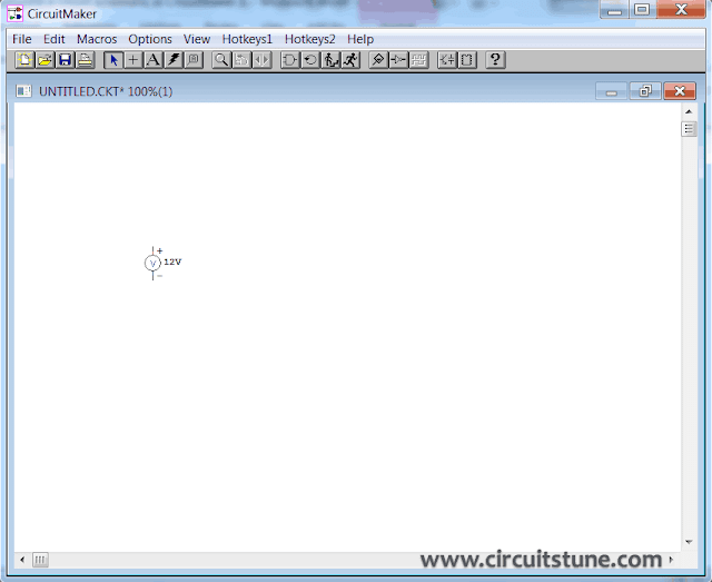
Now place the symbol where you like by left click on mouse .I placed here..


In the same way add a 78L05 regulator IC symbol. See below… 


And place it in workspace.


As same as add a Diode(shortcut key “d”), Capacitor(shortcut key “c”),and Ground(shortcut key “0”) symbol one after one in the same way and place in workspace(see below). To rotate  any device click on device and press “ALT+R”once or two times or as needed.


To see the circuit in zoom view press F2 . Then you see “Circuit Scale” window, enter a value between 10 to 2000 % that you want to scale (I’m entered 150%). And press “ENTER”.

Now the circuit symbol will larger, now we can design the circuit in circuitmaker 5 easily.


Back to adding schematic symbol.

Now add two “Terminal” (see below...)


Do that two times and then rotate as shown below.


Step-3: Connect the circuit.

Select the “Wire tool” (see below…) 


To connect two pins of two device click to pin(1) and drag until to pin(2). See below…

 
Connect all the pins that are necessary (see Fig:1).

After connect the circuit its looks something like this…


Step-4: Simulate the circuit using circuitmaker simulator.


Don’t worry, this is a simple task. But simulation is necessary for a circuit. To determine that it have any error or it giving us the expected output or not.

Before simulate the circuit we have to confirm that the simulation mode is Analog. To select Analog mode click once on “Digital/Analog” button from toolbar. And then the icon will change. See below...


Now click on “Run/Stop” button from toolbar. See below...


If a confirmation massages box come then select “Yes”.

Then you will see the simulation window. See below...

Showing input value of 12V to 5V  dc-dc converter circuit diagram
Showing output value of 12V to 5V  dc-dc converter circuit diagram
 
Note: If you want to change any parts/device/source value in the circuit, double click on the parts/device/source and enter your value.

We are all done and you can see in screenshot, the output voltage is 5V DC. And that is our expected output and circuit. If you want to know more about 12Vto 5V  dc-dc converter circuit then follow this link.

Thank you for reading. Have you faced any problem when trying to design the circuit and have I missed anything?

What you think? Should i post more tutorial about circuit design and CircuitMaker 5.

GENERATION OF 1 SEC PULSES SPACED 5 SEC APART

Posted by Unknown Monday, December 23, 2013 0 comments
        This circuit using a dual-timer NE556 can produce 1Hz pulses spaced 5 seconds apart, either manually or automatically. IC NE556 comprises two independent NE555 timers in a single package. It is used to produce two separate pulses of different pulse widths, where one pulse initiates the activation of the second pulse.


       The first half of the NE556 is wired for 5-second pulse output. When slide switch S2 is in position ‘a’, the first time is set for manual operation, i.e. by pressing switch S1 momentarily you can generate a single pulse of 5- second duration. When switch S2 is kept in ‘b’ position, i.e. pins 6 and 2 are shorted, timer 1 in NE556 triggers by itself.
         The output of the first timer is connected to trigger pin 8 of second timer, which, in turn, is connected to a potential divider comprising resistors R4 and R5. Resistor R1, preset VR1, resistor R2, preset VR2, and capacitors C2 and C5 are the components determining time period. Presets VR1 and VR2 permit trimming of the 5-second and 1-second pulse width of respective sections.
        When switch S2 is in position ‘a’ and switch S1 is pressed momentarily, the output at pin 5 goes high for about 5 seconds. The trailing (falling) edge of this 5- second pulse is used to trigger the second timer via 0.1μF capacitor C6. This action results in momentarily pulling down of pin 8 towards the ground potential, i.e. ‘low’. (Otherwise pin 8 is at 1/2 Vcc and triggers at/below 1/3 Vcc level.) When the second timer is triggered at the trailing edge of 5-second pulse, it generates a 1- second wide pulse.
         When switch S2 is on position ‘b’, switch S1 is disconnected, while pin 6 is connected to pin 2. When capacitor C is charged, it is discharged through pin 2 until it reaches 1/3Vcc potential, at which it is retriggered since trigger pin 6 is also connected here. Thus timer 1 is retriggered after every 5-second period (corresponding to 0.2Hz frequency). The second timer is triggered as before to produce a 1-second pulse in synchronism with the trailing edge of 5-second pulse.

Inductorless 3 5 Volts Converter

Posted by Unknown Wednesday, October 2, 2013 0 comments
By configuring a comparator and a transistor to control the oscillator in a charge pump circuit, you enable the pump to generate a regulated output of in principle any desired value. Charge pump ICs can either invert or double an input voltage (for example, 3 V to –3 V or 3 V to 6 V). The charge pump itself does not regulate the output voltage and one running off 3 V is not normally capable of generating intermediate output voltage levels like 5 V. However, by adding a comparator and a reference device, you can create arbitrary output levels like 5 V and regulate them as well. Charge pump IC1 (a MAX660) has an internal oscillator whose 45 kHz operation transfers charge from C1 to C2, causing the regulated output to rise.
Inductorless 3-to-5 Volts Converter circuit schematic

When the feedback voltage (pin 3 of IC2) exceeds 1.18 V, the output of comparator IC2 (a MAX921) goes high, turning off the oscillator via T1. The comparator hysteresis (easily added on IC2) is zero here simply because no hysteresis is required in the control loop. The oscillator when enabled generates two cycles, which is sufficient to drive VOUT slightly above the desired level. Next, the feedback turns the oscillator off again. The resulting output ripple will depend mainly on the input voltage and the output load current. Output ripple may be reduced at the expense of circuit efficiency by adding a small resistor (say, 1 ?) in series with C1. You’ll find that ripple also depends on the value and ESR associated with C1 - smaller values of C1 transfer less charge to C2, producing smaller jumps in V OUT.

5 3W Amplifier With Surround System

Posted by Unknown Monday, September 30, 2013 0 comments

The AN7147 Dual 5.3-watt Audio Power Amplifier from Panasonic is listed as a ‘replacement type’ so hopefully will be around for some time to come. Together with some extra components, it can represent a simple surround-sound system requiring no opamps or a negative voltage supply. As shown by the circuit diagram the basic stereo amplifier is changed into a surround-sound system by a trick called ‘adding feedback from the opposite channel’. When surround sound is required, the negative feedback signals supplied by C13-R3 and C12-R4 are fed to the inputs of the ‘other’ amplifier. The resulting phase difference causes the surround effect. If surround sound is not required, the effect can be disabled by pressing push-button S1.

Circuit diagram :

Simple_Surround_Amplifier_Circuit_Diagram5.3W Amplifier With Surround System Circuit Diagram

This causes the bistable built around IC2.A and IC2.B to toggle and drive transistors T1 and T2 such that the above mentioned negative feedback signals are effectively shunted to ground. A high-efficiency LED and a 3.3-kΩ series resistor (R14) should be used to make sure the maximum output current of the CMOS 4001 device is not exceeded. The amplifier should not be loaded with impedances smaller than 3Ω. The AN7147 will typically supply up to 4.3 watts into 4 Ω. The SIL-12 case needs to be cooled wit a small heatsink of about 6 K/W or better. The quiescent current is modest at just 19 mA.

Source : www.extremecircuits.net

Make 5 1 Channel Audio Amplifier

Posted by Unknown Saturday, August 10, 2013 0 comments
5.1 channel amplifier consists of 6 amplifiers 1 channel mono, which has certain specifications on each canals. Has 6 channel surround sound amplifier that consists of Front Left ,Center,Front Right ,Rear Left (Left Surround),Rear Right (Right Surround) , and LFE (Subwoofer).For clarity I give a simple illustration of the layout and the circuit for these speakers.

5.1 Speaker Setup
5.1 Speaker Setup

Accoustic Field Generator
Acoustic Field Generator is generating acoustic sound with surround effects are adjustable with a standard Dolby Surround, able to produce surround sound is good enough but not too much need of funds. Technological developments as if not only focused on one area alone but on all fronts. The development of technologies that exist today one of them is in the field of audio. With more advanced audio technology today not only as mere entertainment but has become a hobby, hobby is not cheap of course. Many audio enthusiasts trying to make music sound that sounded to be very hard to make music sound as live, the addition of the amplifier, woofer or special speakers that cost is not cheap.

The sound effects are living seems to now is something that most do not have to exist in every good audio devices. This effect is basically a surround effect that can lead to sound as though coming from different directions and his voice can still be heard clearly. Currently Compo-tape tape that has been a lot of these facilities surround sound but not good enough when heard from a considerable distance because of the effects surroundnya missing. This is because the distance is too far listener and speaker, speaker layout is not quite right, or the effect of unfavorable surround.


Surround effects are nice and can be heard with a good surround system is a system that is in movie theaters and to make it not a bit prangkat needed funds. However, if satisfaction remains the number one then the fund is not a major problem. To find a middle ground between price and quality surround effects it was attempted to make the Acoustic Field Generator that can produce surround sound is good enough but not too much need of funds. Acoustic Field Generator is capable of generating acoustic sound with surround effects are adjustable with a standard Dolby Surround.


Accoustic Field Generator Construction

Basically an Acoustic Field Generator built from op-amp circuit and filters. Op-amps are usually used as a voltage amplifier in the Acoustic Field Generator is more widely used as active filters. The filter in the tool is very instrumental in creating an acoustic sound that is really clear, but in practice, almost all the filters, do not miss the precision of the signal with a specific frequency. An op-amp is good for this application is the op-amp which has a wide bandwidth, rise time, slew rate and fast setting timenya. In addition to op-amp and active filter, theres more important parts of the power supply. This is the part that is instrumental in creating excellence acoustic sound because of the bad power supply which is the only producer of noise, which will enter into a voice signal path so that should clear acoustic sound into an acoustic sound with the addition of reverberation (noise). The power supply used is the twin power supply + / - 18 volts DC. Part Acoustic Field Generators


Before we start doing this project, it helps us know in advance about the function of each speaker.


Front Channel

Channel Front is a forward channel input signal LR. LR signal is passed to an amplifier with gain = 1 so that this signal is passed without change / to filter the input signal LR. Front Left and Front Right, is a public speaker that we encountered in stereo amplifier, consisting of a woofer and tweeter. Woofers generally produce low tone sound with a frequency range ranging from 80Hz - 250Hz, while the tweeter produces a high tone with a frequency range between 15kHz - 20kHz. For projects that we will create, its good we use a good quality woofer, with a size of 10 inches and a type piezoelectric tweeter for each speaker fronts.


Front Channel 5.1 Amplifier


Center Channel

Center, the fullrange speakers, which produce sound with a frequency range between 80Hz - 10Khz. Output from the center speaker is a summation of left and right signal (left + right = center). In a movie or song Dolby Surround format, commonly used center for dialogue / vocal or speech of the actor / artist of a film and to produce a sound that moves ahead of us.


Center Channel 5.1 Amplifier


Rear Channel with Surround System

In this section is the core of this hard perangakat. These sections produce surround effects. To produce the surround effect is required special IC MN3005 / 8 and MN3101. Both these ICs will delay the incoming signal in several phases, so that the signal output from this phase will be left with a signal phase of the signal lain.Pada this section L and R are deducted (LR) and then passed in the buffer, filter LPF, delay line, filter LPF (7KHz) and the last is a splitter between the signals R and L. Circuit which causes the surround effect is 75KHz LPF circuit that produces its output fed to the Right Rear 75KHz LPF amplifier input while it diparalel with the Left Rear amplifier input so as to produce two signals L and R which is basically a LR signal a phase lag with the original signal phase.


Rear Left and Rear Right, also known as surround speakers. This speaker is generally a semi-midrange speaker (usually used on television or Mini Compo), commonly called satellite speakers. In a movie surround speakers are used to generate the audible sound of distant voices or sounds that move from the back of our approach. In a music surround speakers produce sound backing vocals and generally sounds like guitars, violins and trumpets sounded clear here.
Rear Channel 5.1 Amplifier


Subwoofer Channel

Part of this subwoofer is the summation of inputs L and R inputs to a summing amplifier. The output of the summing amplifier is passed to a class 2A LPF which will only pass signals with frequency rendah.Subwoofer, sometimes referred to as LFE (Low Frequency Effect). For these speakers using a subwoofer speaker. Speaker woofer speaker subwoofer is designed specifically to be able to respond to sound with a very low frequency, ranging from 15Hz - 120Hz. For low tone effect can be produced by either (without any harmonic frequency), then the acoustic box / box speakers are also designed specifically with a variety of methods (there are no visible speaker / inside the box, there are that use insulation / labyrinth, etc. ), so that the speaker is capable of compressing the air effectively, so that will feel the effect.

Subwoofer Channel 5.1 Amplifier


Wiring Diagram Home Theater Amplifier / 5.1 Amplifier