Schematic | Circuit guide | Manual Wiring diagram | Electronic
Showing posts with label meter. Show all posts

Meter Adaptor With Symmetrical Input

Posted by Unknown Tuesday, October 8, 2013 0 comments
In contrast to an ordinary voltmeter, the input of an oscilloscope generally has one side (GND) connected to ground via the mains lead. In certain situations this can be very problematic. When the measuring probe is connected to a circuit that is also connected to ground, there is a chance that a short is introduced in the circuit. That the circuit, and hence the measurement, is affected by this is the least of your problems. If you were taking measurements from high current or high voltage (valve equipment) circuits, the out-come could be extremely dangerous! Fortunately it is not too difficult to get round this problem.

All you have to do is make the input to the oscilloscope float with respect to ground. The instrumentation amplifier shown here does that, and functions as an attenuator as well. The AD621 from Analog Devices amplifies the input by a factor of 10, and a switch at the input gives a choice of 3 ranges. A ‘GND’ position has also been included, to calibrate the zero setting of the oscilloscope. The maximum input voltage at any setting may never exceed 600 VAC. Make sure that R1 and R8 have a working voltage of at least 600 V. You could use two equal resistors connected in series for these, since 300 V types are more easily obtainable.

Meter Adapter With Symmetrical Input circuit schematic

You should also make sure that all resistors have a tolerance of 1% or better. Other specifications for the AD621 are: with an amplification of 10 times the CMRR is 110 dB and the bandwidth is 800 kHz. If you can’t find the AD621 locally, the AD620 is a good alternative. However, the bandwidth is then limited to about 120 kHz. The circuit can be housed inside a metal case with a mains supply, but also works perfectly well when powered from two 9V batteries. The current consumption is only a few milliamps. You could also increase R9 to 10 k to reduce the power consumption a bit more.

Linear RF Power Meter Circuit

Posted by Unknown Thursday, August 8, 2013 0 comments
The National Semiconductor LMV225 is a linear RF power meter IC in an SMD package. It can be used over the frequency range of 450 MHz to 2000 MHz and requires only four external components. The input coupling capacitor isolates the DC voltage of the IC from the input signal. The 10-k? resistor enables or disables the IC according to the DC voltage present at the input pin. If it is higher than 1.8 V, the detector is enabled and draws a current of around 5–8 mA. If the voltage on pin A1 is less than 0.8 V, the IC enters the shutdown mode and draws a current of only a few microampères. The LMV225 can be switched between the active and shutdown states using a logic-level signal if the signal is connected to the signal via the 10-kR resistor.
 
Circuit diagram:
linear-rf-power-meter-circuit-diagram1 Linear RF Power Meter Circuit Diagram
 
The supply voltage, which can lie between +2.7 V und +5.5 V, is filtered by a 100nF capacitor that diverts residual RF signals to ground. Finally, there is an output capacitor that forms a low-pass filter in combination with the internal circuitry of the LMV225. If this capacitor has a value of 1 nF, the corner frequency of this low-pass filter is approximately 8 kHz. The corner frequency can be calculated using the formula fc = 1 ÷ (2 p COUT Ro) where Ro is the internal output impedance (19.8 k?). The output low-pass filter determines which AM modulation components are passed by the detector.

rf-power-meter-circuit-diagram2
The output, which has a relatively high impedance, provides an output voltage that is proportional to the signal power, with a slope of 40 mV/dB. The output is 2.0 V at 9 dBm and 0.4 V at –40 dBm. A level of 0 dBm corresponds to a power of 1 mW in 50 R. For a sinusoidal wave-form, this is equivalent to an effective voltage of 224 mV. For modulated signals, the relationship between power and voltage is generally different. The table shows several examples of power levels and voltages for sinusoidal signals. The input impedance of the LMV225 detector is around 50 R to provide a good match to the characteristic impedance commonly used in RF circuits.

The data sheet for the LMV225 shows how the 40-dB measurement range can be shifted to a higher power level using a series input resistor. The LMV225 was originally designed for use in mobile telephones, so it comes in a tiny SMD package with dimensions of only around 1 × 1 mm with four solder bumps (similar to a ball-grid array package). The connections are labelled A1, A2, B1 and B1, like the elements of a matrix. The corner next to A1 is bevelled.

Streampowers

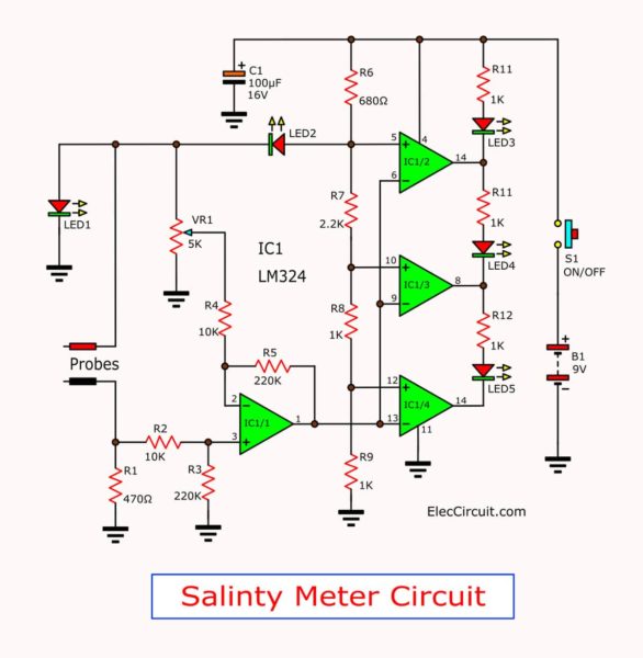
The food salt salinity tester meter circuit

Posted by Unknown Sunday, April 7, 2013 0 comments
A Salt
intake in large quantities is not good for the body and also causes of
diseases such as kidney disease, high blood pressure, heart disease and
paralysis. We should not eat too much. But the recognition of
salinity, but may differ. Therefore should be a good barometer. I
highly recommend The food salt & salinity tester meter circuit,
because it is simple circuit and cheap too.
The circuit ideals.

We use the comparator circuit by an op-amp IC. Which is the difference
between the volume resistance or conductivity of the solution foods has
salt is constituent. In with sensing probe immersed or dunk in the
water or food. Then Showing amount of salt much, Appropriate salinity,
and a little salinity with 3 different LED colors.
the-food-salt-salinity-tester-meter-circuit
How the circuit works.

The circuit ready running When dipping or dip the probe into the
solution or food. Then press switch-S1, by has IC1/1(LM324) amplify a
differential signal, the voltage output at pin 1 as quantities
resistance or conductivity of the solution foods has salt component is
measured through the probe.
Which if a water or foods with little
salt as an ingredient. The resistance is quite high. Less current to
flow through it. The voltage comparator circuit so has the output at
pin 1 a few, As a result output at pin 14, pin 8 and pin 7 of
IC1/4,IC1/3 and IC1/2(LM324) have all high state, makes the LED5, LED4
and LED3 not glow.
Water or food, that have a salt is very
complement. Resistance is relatively low. Current to flow through much,
makes the output signal at pin 1 much into the voltage comparator
circuit , as a result the output at pin 14, pin 8 or pin 7 of IC1/4,
IC1/3 and IC1/2 has state is high only one or all, makes LED5,LED4 or
LED3 in order to light up.
Additional will use LED5 yellow. If
brightness is represented by the amount of salt. With little food or
water. If the green light is LED4 is represented by the amount of salt
in food or water has Fitted. And the LED3 will light red when the user
is represented by the amount of salt in food or water is too much.