Schematic | Circuit guide | Manual Wiring diagram | Electronic
Showing posts with label system. Show all posts

Pump Controller For Solar Hot Water System

Posted by Unknown Saturday, October 5, 2013 0 comments
This circuit optimizes the operation of a solar hot water system. When the water in the solar collector is hotter than the storage tank, the pump runs. The circuit comprises two LM335Z temperature sensors, a comparator and Mosfet. Sensor 1 connects to the solar collector panel while Sensor 2 connects to the hot water panel. Each sensor includes a trimpot to allow adjustment of the output level. In practice, VR1 and VR2 are adjusted so that both Sensor 1 and Sensor 2 have the same output voltage when they are at the same temperature. The Sensor outputs are monitored using comparator IC1.

When Sensor 1 produces a higher voltage than Sensor 2, which means that sensor 1 is at a higher temperature, pin 1 of IC1 goes high and drives the gate of Mosfet Q1. This in turn drives the pump motor. IC1 includes hysteresis so that the output does not oscillate when both sensors are producing a similar voltage. Hysteresis comprises the 1MO feedback resistor between output pin 1 and non-inverting input pin 3 and the input 1kO resistor. This provides a nominal 12mV hysteresis so that voltage at Sensor 1 or Sensor 2 must differ by 12mV for changes in the comparator output to occur.

Pump controller for solar hot water system circuit schematic

Since the outputs of Sensor 1 and Sensor 2 change by about 10mV/°C, we could say that there is a degree of hysteresis in the comparator. Note that IC1 is a dual comparator with the second unit unused. Its inputs are tied to ground and pin 2 of IC1 respectively. This sets the pin 7 output high. Since the output is an open collector, it will be at a high impedance. Mosfet Q1 is rated at 60A and 60V and is suitable for driving inductive loads due to its avalanche suppression capability. This clamps any inductively induced voltages exceeding the voltage rating of the Mosfet.

The sensors are adjusted initially with both measuring the same temperature. This can be done at room temperature; adjust the trimpots so that the voltage between ground and the positive terminal reads the same for both sensors. If you wish, the sensors can be set to 10mV/°C change with the output referred to the Kelvin scale which is 273K at 0°C. So at 25°C, the sensor output should be set to (273 + 25 = 298) x 10mV or 2.98V.

Note:

The sensors will produce incorrect outputs if their leads are exposed to moisture and they should be protected with some neutral cure silicone sealant. The sensors can be mounted by clamping them directly to the outside surface of the solar collector and on an uninsulated section of the storage tank. The thermostat housing is usually a good position on the storage tank.

5 3W Amplifier With Surround System

Posted by Unknown Monday, September 30, 2013 0 comments

The AN7147 Dual 5.3-watt Audio Power Amplifier from Panasonic is listed as a ‘replacement type’ so hopefully will be around for some time to come. Together with some extra components, it can represent a simple surround-sound system requiring no opamps or a negative voltage supply. As shown by the circuit diagram the basic stereo amplifier is changed into a surround-sound system by a trick called ‘adding feedback from the opposite channel’. When surround sound is required, the negative feedback signals supplied by C13-R3 and C12-R4 are fed to the inputs of the ‘other’ amplifier. The resulting phase difference causes the surround effect. If surround sound is not required, the effect can be disabled by pressing push-button S1.

Circuit diagram :

Simple_Surround_Amplifier_Circuit_Diagram5.3W Amplifier With Surround System Circuit Diagram

This causes the bistable built around IC2.A and IC2.B to toggle and drive transistors T1 and T2 such that the above mentioned negative feedback signals are effectively shunted to ground. A high-efficiency LED and a 3.3-kΩ series resistor (R14) should be used to make sure the maximum output current of the CMOS 4001 device is not exceeded. The amplifier should not be loaded with impedances smaller than 3Ω. The AN7147 will typically supply up to 4.3 watts into 4 Ω. The SIL-12 case needs to be cooled wit a small heatsink of about 6 K/W or better. The quiescent current is modest at just 19 mA.

Source : www.extremecircuits.net

How to Build a Dual Axis Solar Tracker System Mechanism and Control Circuit Explained

Posted by Unknown Sunday, May 26, 2013 0 comments

The circuit and the mechanism explained in this article may be considered as the easiest and perfect dual axis solar tracker system. 

The device is able to track the daytime motion of the sun precisely and shift in the vertical axis accordingly.

 The device also effectively tracks the seasonal displacement of the sun and moves the entire mechanism in the horizontal plane or in a lateral motion such that the orientation of the solar panel is always kept in a straight axis to the sun so that it complements the vertical actions of the tracker appropriately.


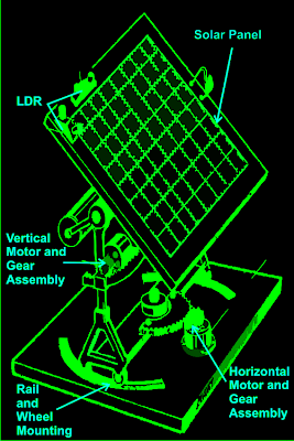
As shown in the figure, a relatively easy mechanism can be witnessed here. The solar tracker is basically mounted over a couple of stand with a central movable axis.

The pivotal arrangement allows the panel mounts to move on a circular axis over almost 360 degrees.

A motor gear mechanism as shown in the diagram is fitted just at the corner of the pivotal axis in such a way that when the motor rotates the entire solar panel shifts proportionately about its central pivot, either anticlockwise or clockwise, depending upon the motion of the motor which in turn depends on the position of the sun.

The position of the LDRs are critical here and the set of LDR which corresponds to this vertical plane movement is so positioned that it senses the sun light accurately and tries to keep the panel perpendicular to the sun rays by moving the motor in the appropriate direction through a definite number of stepped rotations.

The LDR sensing is actually accurately received and interpreted by an electronic circuit which commands the motor for the above explained actions.

Another mechanism which is quite similar to the above vertical setting, but moves the panel through a lateral motion or rather it moves the whole solar panel mount in circular motion over the horizontal plane.

This motion takes place in response to the position of the sun during the seasonal changes, therefore in contrast to the vertical movements; this operation is very gradual and cannot be experienced on a daily basis.

Again the above motion is in response to the command given to the motor by the electronic circuit which operates in response to the sensing done by the LDRs.

For the above procedure a different set of LDRs are used and are mounted horizontally over the panel, at a specific position as shown in the diagram.

How the Solar Tracker Control Circuit Functions

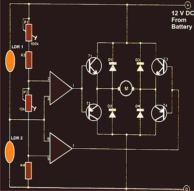
A careful investigation of the circuit shown in the diagram reveals that the whole configuration is actually very simple and straightforward. Here a single IC 324 is utilized and only two of its op amps are employed for the required operations.

The op amps are primarily wired to form a kind of window comparator, responsible for activating their outputs whenever their inputs waver or drift out of the predetermined window, set by the relevant pots.
Two LDRs are connected to the inputs of the opamps for sensing the light levels.

As long as as the lights over the two LDRs are uniform, the outputs of the opamp remain deactivated.

However the moment one of the LDRs senses a different magnitude of light over it (which may happen due to the changing position of the sun) the balance over the input of the opamp shift toward one direction, immediately making the relevant opamps output go high.

This high output instantly activates the full bridge transistor network, which in turn rotates the connected motor in a set direction, such that the panel rotates and adjusts its alignment with the sun rays until uniform amount of light is restored over the relevant set of LDRs.

Once the light level over the relevant LDR sets is restored, the opamps again become dormant and switch off their outputs and also the motor.

The above sequence keeps on happening for the whole day, in steps, as the sun alters its position and the above mechanism keeps shifting in accordance to the suns position.

It should be noted that two sets of the above explained circuit assemblies will be required for controlling the dual actions or simply to make the above discussed dual tracker solar system mechanism.

Parts List

R3 = 15K,
R4 = 39K,
P1 = 100K,
P2 = 22K,
LDR = Normal type with a resistance of around 10 K to 40K in daylight under shade and infinite resistance in complete darkness.
Op-amps are from IC 324 or separately two 741 ICs may also be incorporated.
T1, T3 = TIP31C,
T2,T4 = TIP32C,
All diodes are 1N4007
Motor = As per the load and size of the solar panel

Courtesy - Elector Electroniks India

Self Installation of Auto Sound System can Save Serious Cash

Posted by Unknown Tuesday, April 9, 2013 0 comments
If you are seriously hoping to save a significant chunk of change when it comes to your auto sound system, you should consider saving on installation. Under ordinary circumstances I urge people to be very, if not overly cautious when it comes to installing your own auto sound systems. The thing is, that some people really are talented when it comes to activities such as this. Beyond talent, some people have frightening skills with electronics and if you are one of those, then by all means consider the money you could save yourself (or the extra money youd have to invest in your system?).


We all know that money doesnt grow on trees and when youve been saving up for quite a while to get the sound system you really want its a serious joy killer to have to wait another month or two in order to save up enough money to cover the cost of the installation of your sound system. If you or someone you know and trust (trust being the operative word in this instance) can do the work, it makes no sense from a fiscal point of view to pay someone else to do it.

That being said, if there are any doubts about your skill or experience you might want to at the very least get a second opinion or price installations in your area to see if it might actually be worth saving a little more. Time is another important issue when it comes to the installation of an auto sound system. It doesnt matter how capable you are of making the installation if you simply lack the time to do it. In cases such as this it would have been just as wise to go ahead and pay someone to make the installation. It makes much more sense to me than having the system sitting in a box for months on end while you wait for the time to get it taken care of.

I am one of those people who firmly believes that time is money. Time lost from work is expensive. This is especially true when the times of 10 or more people are lost. It adds up quickly no matter if you have a small or a large company. Time is also (unfortunately) the one commodity in life that you can never recover. No matter how hard you try you cannot recapture time that has been lost. If you have children you know exactly what Im talking about (particularly if your children are either teens or grown and gone). You cannot recover lost time so make sure you arent wasting your time by trying to install an auto sound system that is beyond your abilities.

Dont fret though. Most of us find that at some point in our lives we are limited by either time or money if not both. If everything was quick and easy we wouldnt really have anything worth working for would we? Consider all your limitations when planning and purchasing your auto sound system and make sure that the system you select falls squarely within your ability to install, your time limit for installation, or your price range for affording to pay for the installation. Whether you decide to do your own installation or have a professional installation of your auto sound system the prize is the superior sound quality you will be able to enjoy.