Schematic | Circuit guide | Manual Wiring diagram | Electronic
Showing posts with label dual. Show all posts

Dual Oscillator For Microcontrollers

Posted by Unknown Saturday, January 11, 2014 0 comments
The MAX7378 contains two oscillators and a power-on reset circuit for microprocessors. The Speed input selects either 32.768 kHz (LF) or a higher frequency, which is pre-programmed. The type number corresponds to the standard pre-programmed value and the value of the reset threshold. There is a choice of two threshold values: 2.56 V and 4.29 V.

Both thresholds are available with all standard frequencies, which are 1 MHz, 1.8432 MHz, 3.39545 MHz, 3.6864 MHz, 4 MHz, 4.1943 MHz, and 8 MHz. However, any frequency between 600 kHz and 10 MHz is also possible. An internal synchronization circuit ensures that no glitches occur when switching between the two oscillators. The Reset output of the MAX7378 is available in three different options.


Two of the options are push-pull types, either active low or active high. The third option is open drain, which thus requires an external pull-up resistor. That is the only standard option (which is why a resistor in dashed outline is shown connected to the Reset output). The Reset signal remains active for 100 µs after the supply voltage rises above the threshold voltage.

The Reset signal becomes active immediately if the voltage drops below the threshold. The IC is powered via two separate pins. The VL pin powers the reset and oscillator circuitry, while the VCC pin powers the remainder of the chip. The two pins must always have the same potential. Good decoupling in the form of two 100-nF ceramic capacitors (SMD types) is also necessary.

The IC is housed in the tiny 8-pin µMAX package and has dimensions of only 3.05 × 5.03 mm including pins, with a pin pitch of only 0.65 mm. Unfortunately, the accuracy of the oscillators is not especially good. The HF oscillator has an error of ±2% at 25 °C with a 5-V supply voltage and a maximum temperature coefficient of +325 ppm, which doesn’t exactly correspond to crystal accuracy, but it is certainly usable for most non-time-critical applications.

The error over the full supply voltage range (2.7–5.5 V) is twice as large. The 32.768-kHz oscillator is more accurate, with an error of only 1% at 5 V and 25 °C, although this is still a bit too much for time measurements. The error can be as much as ±3% over the entire supply voltage range. The maximum current consumption is 5.5 mA, which is relatively low.

Dual Power Supply For Amplifiers

Posted by Unknown Sunday, September 22, 2013 0 comments
A power supply suitable for use with the 60W amplifier presented in the predeeding project is perfectly simple, and no great skill is required to build (or design) one. There are a few things one should be careful with, such as the routing of high current leads, but these are easily accomplished. The first thing to choose is a suitable transformer. I suggest toroidal transformers rather than the traditional "EI" laminated types because they radiate less magnetic flux and are flatter, allowing them to be installed in slimmer cases.

They do have some problems, such as higher inrush current at switch on, which means that slow blow fuses must be used. For the 60W amplifier, a nominal (full load) supply of +/- 35V is required, so a 25-0-25 secondary is ideal - however, see Updates, below. The circuit for the supply is shown below, and uses separate rectifiers, capacitors and fuses for each channel. Only the transformer is shared, so channel interactions are minimised. A single ±35V supply (i.e. using only a single bridge and set of filter capacitors) will work just as well in the majority of cases.

Dual Power Supply circuit diagram For AmplifiersThe 5A slow-blow fuse shown is suitable for a 300VA transformer, if a 120VA transformer is used, this should be reduced to 2.5A (or 3A if 2.5A proves too hard to get). If you are even a little bit concerned about the fuse rating, contact the transformer manufacturer for the recommended value for the transformer you will use. The correct fuse is critical to ensure safety from electrical failure, which could result in the equipment becoming unsafe or causing a fire.

The capacitance used is not critical, but is somewhat dependent upon ones budget. I suggest 10,000uF capacitors, but they are rather expensive so at a pinch 4,700uF caps should be fine - especially in the arrangement shown. When unloaded (or with only light load), the voltage will normally be somewhat higher than 35 Volts. This is Ok, and should not cause distress to any amp. The voltage will fall as more current is drawn, and may drop below 35V if a small transformer (or one with unusually poor regulation) is used.

Two parts of this circuit are critical:
  • Mains wiring must be cabled using approved 240V rated insulated cable, and all terminations must be insulated to prevent accidental contact. The mains earth must be securely fastened to the chassis, after scraping away any paint or other coating which might prevent reliable contact.
  • The centre-tap of the transformer and the ground points of each capacitor must be connected to the main signal earth point via heavy duty copper wire, or (preferably) a copper bus-bar. Large currents flow in this part of the circuit, containing nasty current waveforms which are quite happy to invade your amplifier. The supply voltages must be taken from the capacitors (not the bridge rectifiers) to prevent unwanted hum and noise.
When wiring the bridge rectifiers to the transformer, connect exactly as shown to ensure that ripple voltages (and currents) are in phase for each amp. If not, mysterious hum signals may be injected into the amps signal path from bypass capacitors and the like. This is somewhat unlikely unless huge caps are used on the amp board(s) - not recommended, by the way - but why take the risk?

Bridge rectifiers should be the big bolt-down 35A types (or something similar) to ensure lowest possible losses (these will not require an additional heatsink - the chassis will normally be quite sufficient). The transformer primary voltage will obviously be determined by the supply voltage in your area (i.e. 120, 220 or 240) and be suited to the local supply frequency. Note that all 50Hz transformers will work just fine at 60Hz, but some 60Hz devices will overheat if used at 50Hz.

The transformer should be rated at a minimum of 120VA (Volt-Amps) for home use, but a 300VA transformer is recommended due to its superior regulation. Going beyond 300VA will serve no useful purpose, other than to dim the lights as it is turned on. Where it is possible, the signal and power ground should be the same (this prevents the possibility of an electric shock hazard should the transformer develop a short circuit between primary and secondary. Where this will give rise to ground loops and hum in other equipment, use the method shown.

The resistor R1 (a 5W wirewound resistor is suggested) isolates the low-voltage high-current ground loop circuit, and the diodes D1 & D2 provide a protective circuit in the event of a major problem. These diodes need only be low voltage, but a current rating of 5A or greater is required. The 100nF capacitor (C1) acts as a short circuit to radio frequency signals, effectively grounding them. This should be a device with very good high frequency response, and a monolithic ceramic is recommended.

Updates:

The transformer secondary voltage will probably need to be higher than described above. I tested some stock and custom transformers I have, and found that unless the transformer has extraordinarly good regulation, a nominal 28-0-28 secondary will be needed, more with an average (i.e. poor) regulation unit. Also be careful when you test, since a relatively small (10%) variation in the mains voltage makes a big difference to measured output power - the secondary voltage also falls by 10%, so 60W becomes 48W if the mains is 10% low.

You also need to remember that the output voltage of transformers is typically quoted at full power with a resistive load. This means two things:
  1. The no load voltage will be higher than expected
  2. The loaded voltage will be lower than expected
The first point is true because there is no loading, so the output voltage must rise. The second is more complex, but happens because the conventional rectifier circuit uses a capacitor input filter (the rectifier feeds directly into the capacitor(s)). Since the diodes only conduct at the peak of the waveform, the current is much higher, so the transformer and supply line impedance will cause the peak voltage to fall, and the DC voltage cannot exceed the peak output voltage (less two diode forward voltage drops).
Source: http://sound.westhost.com/project04.htm

Dual 3 Way Indoor Outdoor Speaker Set LU43

Posted by Unknown Tuesday, August 6, 2013 0 comments
The DUAL LU43 is petite stylish size, but towering on sound. This 3-way multi-point orator is designed to transport accurate astronomical-fidelity sound apart from of placement. The weather-tough design makes the LU43 ideal intended for undying otherwise temporary open-air avail yourself of. incorporated with the LU43 bring out fix is an amendable logo for vertical before horizontal mounting options. The LU43 is by national absolutely something like anywhere as well as areas ranging from back yards, patios and pool / spa settings.• Frequency Response 100 Hz-20kHz •Woofer 4 edge your way (100mm) polyelite with PVA Surround • Midrange 40mm poly shaft • Tweeter 20mm Piezo field Sensitivity 85.5 dB (2.83v @ 1 measuring device) • Nominal Impedance 4-6 ohms • Power management 50 watts RMS - 100 watts (IPP) creation Dimensions (L x W x H) 5.52 crawl x 5.52 inch x 8.2 inch.


Technical Details

  • Power handling: 50 watts RMS, 100 watts peak
  • 4-Inch polyelite subwoofer with rubber surround sound
  • 40mm polycone midrange and 20mm piezo tweeter
  • Sensitivity; 87dB, Frequency response: 100Hz-20kHz
  • Aluminum grill (non-removable), rotating logo for versatile mounting options, UV treated ABS enclosure
  • 4-inch woofer, 25mm poly cone midrange, and 20mm Piezo dome tweeter
  • 50 watts of RMS power, with 100 watts of peak power
  • Each speaker measures 8.25 x 5.25 x 5.25 inches (HxWxD); 1-year warranty
  • Pair of multipurpose indoor/outdoor speakers in black for permanent or temporary outdoor use
  • Wall-mountable, UV-treated ABS enclosure; mounting brackets included

Wiring Dual Voice Coil Subs Mono Page

Posted by Unknown Tuesday, June 4, 2013 0 comments
Subwoofer Wiring on How To  Additional Subwoofer System Wiring Connection For Vw Golf Iv
How To Additional Subwoofer System Wiring Connection For Vw Golf Iv.


Subwoofer Wiring on Basic Subwoofer Wiring  For More Information  Check Out Our Subwoofer
Basic Subwoofer Wiring For More Information Check Out Our Subwoofer.


Subwoofer Wiring on Ideally The Power Capacitor Should Be As Close As Possible
Ideally The Power Capacitor Should Be As Close As Possible.


Subwoofer Wiring on Choosing Subwoofer Wiring For Your Passive And Powered Subwoofer Box
Choosing Subwoofer Wiring For Your Passive And Powered Subwoofer Box.


Subwoofer Wiring on Car Stereos  Amp And Subwoofer Wiring   4 Ohm Dvc Sub Or 2ohm Dvc Sub
Car Stereos Amp And Subwoofer Wiring 4 Ohm Dvc Sub Or 2ohm Dvc Sub.


Subwoofer Wiring on Wiring A Sub To Pre Existing Amp Speakers    Honda Tech
Wiring A Sub To Pre Existing Amp Speakers Honda Tech.


Subwoofer Wiring on Subwoofer Wiring Diagrams  Two 2 Ohm Dual Voice Coil  Dvc  Speakers
Subwoofer Wiring Diagrams Two 2 Ohm Dual Voice Coil Dvc Speakers.


Subwoofer Wiring on Wiring Two Dual Voice Coil Subs To One Mono Amp   Page 2
Wiring Two Dual Voice Coil Subs To One Mono Amp Page 2.


Subwoofer Wiring on Need Sum Help Wiring Dual Coil Sub And Box Build     Trinituner Com
Need Sum Help Wiring Dual Coil Sub And Box Build Trinituner Com.


Subwoofer Wiring on Adding A Subwoofer To Bose
Adding A Subwoofer To Bose.


How to Build a Dual Axis Solar Tracker System Mechanism and Control Circuit Explained

Posted by Unknown Sunday, May 26, 2013 0 comments

The circuit and the mechanism explained in this article may be considered as the easiest and perfect dual axis solar tracker system. 

The device is able to track the daytime motion of the sun precisely and shift in the vertical axis accordingly.

 The device also effectively tracks the seasonal displacement of the sun and moves the entire mechanism in the horizontal plane or in a lateral motion such that the orientation of the solar panel is always kept in a straight axis to the sun so that it complements the vertical actions of the tracker appropriately.


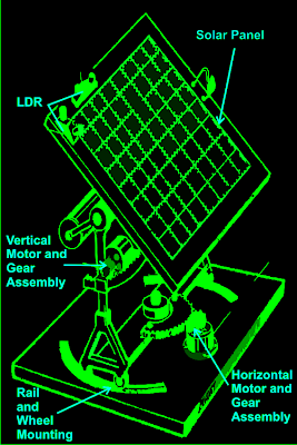
As shown in the figure, a relatively easy mechanism can be witnessed here. The solar tracker is basically mounted over a couple of stand with a central movable axis.

The pivotal arrangement allows the panel mounts to move on a circular axis over almost 360 degrees.

A motor gear mechanism as shown in the diagram is fitted just at the corner of the pivotal axis in such a way that when the motor rotates the entire solar panel shifts proportionately about its central pivot, either anticlockwise or clockwise, depending upon the motion of the motor which in turn depends on the position of the sun.

The position of the LDRs are critical here and the set of LDR which corresponds to this vertical plane movement is so positioned that it senses the sun light accurately and tries to keep the panel perpendicular to the sun rays by moving the motor in the appropriate direction through a definite number of stepped rotations.

The LDR sensing is actually accurately received and interpreted by an electronic circuit which commands the motor for the above explained actions.

Another mechanism which is quite similar to the above vertical setting, but moves the panel through a lateral motion or rather it moves the whole solar panel mount in circular motion over the horizontal plane.

This motion takes place in response to the position of the sun during the seasonal changes, therefore in contrast to the vertical movements; this operation is very gradual and cannot be experienced on a daily basis.

Again the above motion is in response to the command given to the motor by the electronic circuit which operates in response to the sensing done by the LDRs.

For the above procedure a different set of LDRs are used and are mounted horizontally over the panel, at a specific position as shown in the diagram.

How the Solar Tracker Control Circuit Functions

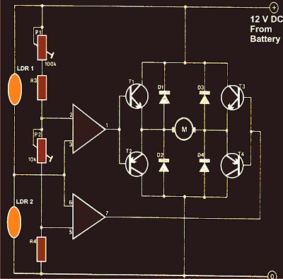
A careful investigation of the circuit shown in the diagram reveals that the whole configuration is actually very simple and straightforward. Here a single IC 324 is utilized and only two of its op amps are employed for the required operations.

The op amps are primarily wired to form a kind of window comparator, responsible for activating their outputs whenever their inputs waver or drift out of the predetermined window, set by the relevant pots.
Two LDRs are connected to the inputs of the opamps for sensing the light levels.

As long as as the lights over the two LDRs are uniform, the outputs of the opamp remain deactivated.

However the moment one of the LDRs senses a different magnitude of light over it (which may happen due to the changing position of the sun) the balance over the input of the opamp shift toward one direction, immediately making the relevant opamps output go high.

This high output instantly activates the full bridge transistor network, which in turn rotates the connected motor in a set direction, such that the panel rotates and adjusts its alignment with the sun rays until uniform amount of light is restored over the relevant set of LDRs.

Once the light level over the relevant LDR sets is restored, the opamps again become dormant and switch off their outputs and also the motor.

The above sequence keeps on happening for the whole day, in steps, as the sun alters its position and the above mechanism keeps shifting in accordance to the suns position.

It should be noted that two sets of the above explained circuit assemblies will be required for controlling the dual actions or simply to make the above discussed dual tracker solar system mechanism.

Parts List

R3 = 15K,
R4 = 39K,
P1 = 100K,
P2 = 22K,
LDR = Normal type with a resistance of around 10 K to 40K in daylight under shade and infinite resistance in complete darkness.
Op-amps are from IC 324 or separately two 741 ICs may also be incorporated.
T1, T3 = TIP31C,
T2,T4 = TIP32C,
All diodes are 1N4007
Motor = As per the load and size of the solar panel

Courtesy - Elector Electroniks India

Dual Input Combining Stereo Line Amplifier

Posted by Unknown Monday, April 8, 2013 0 comments
This circuit takes two separate line-level stereo (L & R) signals and combines them into one stereo (L & R) output, thus avoiding the need to switch between two pairs of input signals. In the author’s application, it is used to feed the stereo audio from a TV receiver and a DVD player into an external amplifier. The need for the circuit arose because of a design peculiarity in the TV receiver. The TV has four A/V inputs and one A/V output. AV1-AV3 accept composite or S-video plus stereo audio inputs and these feed into the TV’s A/V output. AV4 accepts Component video (Y/Pb/Pr) plus stereo audio but unlike AV1-AV3, its audio (and video) signals are not fed to the TV A/V output. The Y/Pb/Pr input was chosen for use with the DVD player because of its superior video quality, while the audio was to be fed to an external amplifier for improved reproduction.
Circuit diagram:
stereo-line-amplifier-circuit-diagram
Dual Input-Combining Stereo Line Amplifier Circuit Diagram
However, manual switching was inconvenient, hence the genesis of this design. In use, the DVD player audio is fed in parallel to TV AV4 and to one input pair of the combining amplifier, while the TV audio output feeds the other input pair. The amplifier output goes to the external audio amplifier. There is no conflict between the two audio inputs because when AV4 (DVD player) is selected, there is no TV audio output. In all other modes, the DVD player is off. As shown, the circuit has a voltage gain of 1.5 times (3.5dB) but this can be altered as required by changing the two 15kW resistors. Input impedance is 10kW and the outputs are isolated from cable and amplifier input capacitance with 47W series resistors. The circuit can be powered from a regulated 12V DC plugpack.
Author: Garth Jenkinson - Copyright: Silicon Chip Electronics
Source : www.extremecircuits.net