Schematic | Circuit guide | Manual Wiring diagram | Electronic
Showing posts with label and. Show all posts

Bass and Treble Control without any IC and Transistor

Posted by Unknown Friday, December 20, 2013 0 comments
This low cost bass treble circuit consists of some capacitors, resistors, and two T/C pot for BASS and TREBLE control. this circuit can be made without even a veroboard. You just solder components as this circuit network is not so complex. It has only two-pin parts. Let’s take a look at he circuit diagram. Nothing to say about it, as it is so simple that a beginner level hobbyist can even understand and build this circuit.

Bass and Treble Control without any IC and Transistor

But there are some -ve points of this circuit which I must say, after giving you the circuit. As no external power supply, the O/P power is much lesser than I/P power, so volume decreases. The treble control doesn’t act as linear, it increases treble a lot in the end pot side

Simple Power Pulse Using by LM350 and NE555 Circuit Diagram

Posted by Unknown 0 comments
This is a Simple Power Pulse Using by LM350 and NE555 Circuit Diagram. This circuit can use to drive lamp,power LED,DC motor etc. Adjust R5 for output amplitude.Adjust R1 for output power .

Power Pulse Circuit Diagram

Power Pulse Circuit Diagram


The LM350 is adjustable 3-terminal positive voltage regulators is capable of supplying in excess of 3A over a 1.2V to 33V output range.This circuit requires 5-15V power supply.

Cat And Dog Repellent

Posted by Unknown Friday, October 4, 2013 0 comments
The electronic dog repellent circuit diagram below is a high output ultrasonic transmitter which is primarily intended to act as a dog and cat repeller, which can be used individuals to act as a deterrent against some animals. It should NOT be relied upon as a defence against aggressive dogs but it may help distract them or encourage them to go away and do not consider this as an electronic pest repeller. The ultrasonic dog repellant uses a standard 555 timer IC1 set up as an oscillator using a single RC network to give a 40 kHz square wave with equal mark/space ratio.

This frequency is above the hearing threshold for humans but is known to be irritating frequency for dog and cats. Since the maximum current that a 555 timer can supply is 200mA an amplifier stage was required so a high-power H-bridge network was devised, formed by 4 transistors TR1 to TR4. A second timer IC2 forms a buffer amplifier that feeds one input of the H-bridge driver, with an inverted waveform to that of IC1 output being fed to the opposite input of the H-bridge.

This means that conduction occurs through the complementary pairs of TR1/TR4 and TR2/TR3 on alternate marks and spaces, effectively doubling the voltage across the ultrasonic transducer, LS1. This is optimised to generate a high output at ultrasonic frequencies. This configuration was tested by decreasing the frequency of the oscillator to an audible level and replacing the ultrasonic transducer with a loudspeaker; the results were astounding. If the dog repellent circuit was fed by a bench power supply rather than a battery that restrict the available current, the output reached 110dB with 4A running through the speaker which is plenty loud enough!

The Dog and Cat repellent was activated using a normal open switch S1 to control the current consumption, but many forms of automatic switching could be used such as pressure sensitive mats, light beams or PIR sensors. Thus it could be utilize as part of a dog or cat deterrent system to help prevent unwanted damage to gardens or flowerbeds, or a battery powered version can be carried for portable use. Consider also using a lead-acid battery if desired, and a single chip version could be built using the 556 dual timer IC to save space and improve battery life.

Ensured privacy and security

Posted by Unknown Thursday, August 8, 2013 0 comments


The roll-out of smart meters in the UK is expected to help lower carbon emissions in homes and businesses. With the transparency and simplicity they will provide to customers with regards to both billing and understanding energy usage, it is easy to appreciate how smart meters will help the UK to lower its overall carbon emissions and meet the targets it has in place to cut these by 12.5 per cent by 2012. Prosenjit Dutta, head of advanced metering infrastructure (AMI) practice within the utilities division of Infosys and Kush Sharma, utilities lead for UK & Europe, Infosys, explainCommitment has already been shown by one of the country’s largest utility retailers, British Gas, which has plans to install smart meters in 10 millions homes by the end of 2012, and already nPower and EDF have pledged to do the same. Therefore, it is clear to see the UK is in good stead to meet its 2020 target.
However, as increased commitment is garnered and smart meters start to become a reality, consideration needs to move towards ensuring the right back-end IT processes are in place. One of the key areas which needs attention is that of ensuring privacy and security of the data stored on a smart meter and the information being transmitted across the communication network and various support systems.
With cyber attacks and data losses affecting many from an enterprise perspective, consideration into what data could and will be held on smart meters and associated enterprise IT systems about a customer will mean that energy companies will need to make sure that they have the right security controls in place to protect this information. Feedback thus far from some of our utility customers has been that they are faced with  between 800-1000 attacks on their networks each month and whilst this isn’t necessarily strictly related to smart meters, it does highlight the need to ensure that security of these devices are locked in place and maintained.
The solution
So, what can be done to ensure that all this information is protected? A first step is for utility companies to ensure that a full security assessment is completed on their systems and networks to identify any potential security pain points. At the moment, there is no set way in which infrastructure security issues can be identified and anticipated, meaning that more standards are needed to protect not only customer experience, but also their personal information. With the 2020 deadline looming, the foundations need to be set sooner rather than later.
In addition, given the raft of personal information which each utility holds, any losses could have a significant impact not only on customers’ privacy, but also on the reputation of that utility. Therefore smart network security is vital to the success of their business.
Comparing and contrasting examples
Traditionally, security was a reactive task for organisations and was only considered when something went wrong. It is now clear that utilities can no longer rest on their laurels when it comes to the security and privacy capabilities of their network.  Whilst smart security seems like another world for UK utilities, for those in the US, it is already a standard practice and consideration.
Alot can be learnt from American utility companies, with the most important including getting smart meter standards in place from the outset. In the US, the National Institute of Standards and Technology (an agency of the US Department of Energy) oversees not only the management of these standards, but also the development of testing, measurements, and the reference materials needed to ensure the quality of energy-related products and services whilst ensuring fairness in the market.
The good news is that we are already seeing similar steps being taken in the UK. The Government has established a central change programme – the Smart Metering Implementation Programme Prospectus. The prospectus sets out the coalition government’s programme for the introduction of smart meters which is estimated to be worth £7.2 billion. As a result, we are starting to see clients looking to become more proactive with regard to their security processes to future proof their smart meter networks. If privacy and security processes are locked in place from the outset, then this will in turn increase privacy measures to protect customers.
Securing your AMI
However, another key vulnerability for consideration by utility companies could be intrinsic to the smart meter infrastructure deployed. An advanced metering infrastructure (AMI) is widely known to be the basic building block for the smart grid enabled utility of the future; however in an AMI enabled environment, the initial and biggest challenge a utility will face is the surge of customer data and the strain on the network which could expose it to a variety of vulnerabilities.
Key vulnerabilities currently facing AMI ecosystems include:
•    End point devices (Meters, Gateways and Data Collectors) – Denial of Service, Unauthorised Access to devices, Modification of Customer Data, Firmware/ Data Extraction, Circuit Analysis, etc.
•    Communication Network (HAN, WAN backhaul and RF mesh) – Man in the Middle, Masquerade, Service Spoofing, Encryption Key theft, etc.
•    Utilitys Datacentre (Collection engine and upstream systems) – Spurious device reprogramming and remote disconnect requests originating from Customer Information Systems.
To mitigate the risks and vulnerabilities posed by AMI adoption, it is recommended utilities engage in an upstream assessment of their existing systems and AMI impacts. This process has to be iterative and subsequently needs to be practiced even during steady state, once the AMI roll-out starts or is fully completed.
For utilities with AMI deployments in progress, or nearing completion, instead of responding to security events in a reactive mode, they should proactively pull data from smart meters at defined intervals and run correlation logics to identify and subsequently address possible vulnerabilities. Based on our observation, most utilities are currently handling AMI security threats in a reactive mode, which clearly needs to be changed.
It is therefore important utilities modify their strategy to handle threats in a proactive method by gathering near-real time information from smart meters. The adoption of proactive security practices in an AMI ecosystem should be enabled with real-time dashboards that alert systems administrators of possible attacks. This should be backed up by tools to counter such attacks. The result will be a system that is made progressively secure.
What to remember – five little things
In order to maintain privacy and security of customer data and the network, there are five key areas which utility companies must consider protecting.
The first that needs to be considered is that of electronic perimeter security. Given the range in size and scale of the communications infrastructure (which can vary depending on the size or geographic spread of your customer base), it is vital that the energy or utility company has the IT system in place to support this. In particular, a variety of wireless and terrestrial technologies pose a challenge to adopt common and more streamlined security architecture.
Secondly, by fully ensuring the security of the smart device itself, this takes into account the authentication and authorisation of a large number of end point devices such as smart meters or data collectors to the utilities network. This must consider the integration of these proprietary end point devices to enterprise standard security technologies. It is important therefore, to protect these end points from unauthorised access from wireless networks in particular.
Currently, the regulatory standards which are in place lack those of mature and established frameworks to support AMI security. As a result, many isolated and proprietary AMI standards are still being promoted by utilities as there are currently no mandated security standards for them to follow. Therefore, by ensuring that these are agreed up front allows for a clear focus for all.
As we know, sensitive customer information is stored and transmitted from smart meters. Given the recent cyber security attacks, this further shows how wireless enabled smart meters are highly vulnerable to security breaches – something which, as discussed, needs to be addressed.
Finally, the vast and often, remote number of unmanned substations pose enormous physical security challenges to any utility company. Therefore, it is important to ensure that devices, such as smart meters, can be protected from tampering.
Once each of these areas are considered, the first steps towards ensuring security controls will be in place to protect customer data on smart meters. However, if there is one thing which should be thought about over and above this, is to ensure that proactivity is maintained at all times. If we could all be a little bit more proactive when protecting customer information or fixed an issue before it became a problem, more could be done now to protect not only the company’s network, but as a result, customer information.

Guide to the Power Circuit and Control Circuit of the Wound Rotor AC Induction Motor

Posted by Unknown Friday, August 2, 2013 0 comments
In certain exceedingly enormous type of industrial applications where a tremendous amount of power is required to drive a specific type of load too large for the ordinary type squirrel cage induction motors to carry, the most appropriately preferred type of motor for use with such extensively large demand of power application is another type of large capacity motor which has the capability to run with high starting torque immediately attainable all throughout starting from when the motor is just beginning to run from rest even while it is at loaded condition up to when the motor reaches its peak rated speed while also carrying the same amount of heavy load, which would also necessitate for this type of motor to possess the ability to run continuously at different variation of steps of speed levels while driving a very heavy load. This type of motor is known as the wound rotor induction motor.


This so-called wound rotor motor as the name implies is a type of AC induction motor which does not only have stator windings but is also equipped with rotor windings. The terminal ends of its rotor windings are externally connected to slip rings and brushes as part of the motor assembly where these rotor winding terminates to terminal ends which are wired externally and connected further to an isolated resistor bank which is a separate necessary component to accompany the intended function of the motor to serve its purpose as a one whole complete functioning unit. The separate resistor bank unit connected to the motors wound rotor can be externally switched on and off at different intervals of resistor branches in the resistor bank, thus providing multiple stages of speed levels and torque capacity with an acceleration rate faster than would an ordinary induction motor could accomplish for similar types of bulky load applications to be driven.

Another purpose of the resistor bank connected to the rotor winding is to facilitate for the reduction of the very high inrush starting current, considering that the type of application that the motor will be subjected to requires for the motor to start running at a very heavy load condition.

The resistor bank also serves to absorb the heat developed in the rotor winding which is necessary for the intended application of the motor which is to have the ability to effectively dissipate the heat generated in such extreme load conditions, because rapid heat build-up is an inherent characteristic of very large capacity motors operating at very high load condition from zero speed up to its rated maximum speed or even when running the motor in any continuous variation of speed level falling anywhere within the various stages of speed range of the motor.
Fig-1 below shows an electrical schematic diagram of a three phase power circuit of a wound rotor motor. As shown in the drawing, you will notice that the motor consists of a stator winding which is the stationary part of the motor while another component of the motor is the rotor winding which constitutes the rotating part of the motor.

The stator winding is directly connected to the three phase power supply which provides the source voltage to the motor. The main supply voltage is supplied to the primary side of the disconnect fuse on the three phase terminals L1, L2 and L3 where the fuse serves as an instantaneous interrupting means with rapid action that immediately detects line side power trouble and motor circuit problem such as over voltage, over current, short circuit or overloads. The Main Magnetic Contactor (MMC) is a magnetic motor starter which serves as the motor operation switch which is electrically activated and deactivated remotely with an external push button switch in the control circuit. The overload relay is another type of overload protection device which is directly concentrated in instantaneously detecting motor overload currents that once detected would instantly trip-off to open the control circuit in order to deactivate the main magnetic contactor (MMC) to isolate power flow from the main supply line voltage going to the motor in order to prevent the destruction of the motor.
Fig-1: Electrical Schematic Diagram of the Power Circuit of a Wound Rotor Motor
The secondary part of the wound rotor motor contains the rotor winding. Fig-1 above shows the rotor winding connected to a resistor bank which consists of three resistors per phase making up a total of nine resistors in the entire resistor bank network. There are correspondingly three branches of resistors in the resistor bank which consists of the first branch comprising R1-R2-R3 resistors, the second branch being R4-R5-R6, and finally the last branch contains R7-R8-R9 respectively. Each stages of resistor branches are provided with their own individual magnetic contactor switches with MC1 for the first resistor branch, then MC2 for the second resistor branch and finally MC3 for the third resistor branch. Each of these resistor branches are shorted individually by MC1, MC2 and MC3 according to an order of operational sequence relative to the efficient running of the wound rotor motor.

The single phase step down transformer is made available in Fig-2 above is an electrical schematic diagram of a common control circuit which illustrates how the wound rotor motor is operated to run from standstill until it reaches its rated speed. The power supply source voltage of the control circuit is taken directly from the step down transformer provided in the power circuit in Fig-1 above which shows the reference terminals RC and SC coming from the secondary part of the step down transformer from the power circuit. The proper sequence of operation of the wound rotor motor is directly dependent on the construction of the control circuit based on the intended sequence of operation for this particular wound rotor motor.

The start operation sequence in the control circuit in Fig-2 above begins with the closing of the start push button switch which permits power flow to the main magnetic contactor (MMC) provided that both the stop switch and the overload relay contacts are maintained closed at all times during the operation of the control circuit. The auxiliary open contact of the MMC which is connected in parallel to the start switch serves as the holding contact which maintains the MMC coil energized even after the human operator releases the start switch, this in turn provides continuous power flow to the control circuit which further proceeds in commencing the sequence of steps in the operation of the entire circuit of the wound rotor motor.


During the first stage of the operation of the wound rotor motor when power is connected to the primary stator of the motor, the secondary part or the rotor is firstly connected with maximum resistance with all resistors in the resistor bank network fully active which initially runs the motor at its lowest speed. The flow of electricity in the control circuit would then proceed through the closed contact of Timer 4 going down to the Timer 1 coil which upon reaching its specified time delay period would then activate contactor MC1 to short the first stage resistor branch R1-R2-R3 leaving only the second and third stage of resistor branches to remain active in the resistor network to act on the rotor winding which will eventually increase the speed of the motor to a partial 1/3 of its rated speed.

The activation of contactor MC1 achieves the next step of the operational sequence that closes one of the auxiliary contact of MC1 to energize the Timer 2 coil which upon reaching its specified time delay period would then energize contactor MC2 to short out the second stage resistor branch R4-R5-R6 leaving only the third resistor branch to remain active in the rotor winding which further increases the motor speed to 2/3 of its overall rated speed.

Then comes the last and final stage where the previously activated contactor MC2 energizes the Timer 3 which when its specified time delay period expires would then activate contactor MC3 to totally short out the rotor winding to the fullest without any resistor branches remaining active in the network that can connect to the rotor winding, this final stage brings the motor to run to its fullest rated speed.

The activation of contactor MC3 would then provide a holding contact with one of its auxiliary contact connected in parallel across the Timer 3 contact while maintaining the MC3 coil energized during the final stage of this operational sequence.

This last stage would also activate and maintain the Timer 4 coil which upon reaching its specified time delay period would then open the Timer 4 normally-closed contact to remove power to the coils of Timer 1, MC1, Timer 2, MC2 and Timer 3 in order to release the first stage contactor MC1 and second stage contactor MC2 from shorting out the first and second stages of resistor branches but while also maintaining only the last contactor MC3 to remain activated to maintain the rotor winding shorted out completely hence maintaining the motor to run at its rated full speed.

To interrupt the operation of the circuit, the only thing necessary to manually stop the motor is by pressing the stop switch which would totally remove power to the circuit at any time during the circuit is active no matter under which stage of speed intervals the motor is actively running in. Another interrupting means in the control circuit is the overload relay which automatically shuts down the circuit to immediately stop the motor in case over current is instantly detected at anytime during the motor is running.

How much do the fuel tanks capacities and tank codes for the 1990 Chevrolet Cheyene 2500

Posted by Unknown Wednesday, July 31, 2013 0 comments


How much do the fuel tanks capacities and tank codes for the 1990 Chevrolet Cheyene 2500?


Answer: The short bed is 26 gallon while the long bed is a 34 gallon. You can find the data in the owner’s manual under capacities. A sticker in the glove box should contain all of the RPO codes for your truck.

How to Build a Dual Axis Solar Tracker System Mechanism and Control Circuit Explained

Posted by Unknown Sunday, May 26, 2013 0 comments

The circuit and the mechanism explained in this article may be considered as the easiest and perfect dual axis solar tracker system. 

The device is able to track the daytime motion of the sun precisely and shift in the vertical axis accordingly.

 The device also effectively tracks the seasonal displacement of the sun and moves the entire mechanism in the horizontal plane or in a lateral motion such that the orientation of the solar panel is always kept in a straight axis to the sun so that it complements the vertical actions of the tracker appropriately.


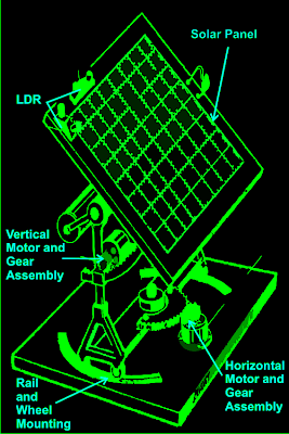
As shown in the figure, a relatively easy mechanism can be witnessed here. The solar tracker is basically mounted over a couple of stand with a central movable axis.

The pivotal arrangement allows the panel mounts to move on a circular axis over almost 360 degrees.

A motor gear mechanism as shown in the diagram is fitted just at the corner of the pivotal axis in such a way that when the motor rotates the entire solar panel shifts proportionately about its central pivot, either anticlockwise or clockwise, depending upon the motion of the motor which in turn depends on the position of the sun.

The position of the LDRs are critical here and the set of LDR which corresponds to this vertical plane movement is so positioned that it senses the sun light accurately and tries to keep the panel perpendicular to the sun rays by moving the motor in the appropriate direction through a definite number of stepped rotations.

The LDR sensing is actually accurately received and interpreted by an electronic circuit which commands the motor for the above explained actions.

Another mechanism which is quite similar to the above vertical setting, but moves the panel through a lateral motion or rather it moves the whole solar panel mount in circular motion over the horizontal plane.

This motion takes place in response to the position of the sun during the seasonal changes, therefore in contrast to the vertical movements; this operation is very gradual and cannot be experienced on a daily basis.

Again the above motion is in response to the command given to the motor by the electronic circuit which operates in response to the sensing done by the LDRs.

For the above procedure a different set of LDRs are used and are mounted horizontally over the panel, at a specific position as shown in the diagram.

How the Solar Tracker Control Circuit Functions

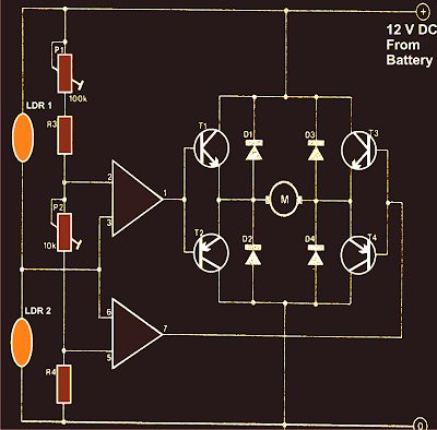
A careful investigation of the circuit shown in the diagram reveals that the whole configuration is actually very simple and straightforward. Here a single IC 324 is utilized and only two of its op amps are employed for the required operations.

The op amps are primarily wired to form a kind of window comparator, responsible for activating their outputs whenever their inputs waver or drift out of the predetermined window, set by the relevant pots.
Two LDRs are connected to the inputs of the opamps for sensing the light levels.

As long as as the lights over the two LDRs are uniform, the outputs of the opamp remain deactivated.

However the moment one of the LDRs senses a different magnitude of light over it (which may happen due to the changing position of the sun) the balance over the input of the opamp shift toward one direction, immediately making the relevant opamps output go high.

This high output instantly activates the full bridge transistor network, which in turn rotates the connected motor in a set direction, such that the panel rotates and adjusts its alignment with the sun rays until uniform amount of light is restored over the relevant set of LDRs.

Once the light level over the relevant LDR sets is restored, the opamps again become dormant and switch off their outputs and also the motor.

The above sequence keeps on happening for the whole day, in steps, as the sun alters its position and the above mechanism keeps shifting in accordance to the suns position.

It should be noted that two sets of the above explained circuit assemblies will be required for controlling the dual actions or simply to make the above discussed dual tracker solar system mechanism.

Parts List

R3 = 15K,
R4 = 39K,
P1 = 100K,
P2 = 22K,
LDR = Normal type with a resistance of around 10 K to 40K in daylight under shade and infinite resistance in complete darkness.
Op-amps are from IC 324 or separately two 741 ICs may also be incorporated.
T1, T3 = TIP31C,
T2,T4 = TIP32C,
All diodes are 1N4007
Motor = As per the load and size of the solar panel

Courtesy - Elector Electroniks India

CONSTANT BRIGNESS LED AND MUTE CONTROL ELECTRONIC DIAGRAM

Posted by Unknown Saturday, April 13, 2013 0 comments

CONSTANT BRIGNESS LED AND MUTE CONTROL ELECTRONIC DIAGRAM

The output power of the modules are approximately 220W to 250W into 8? and 350W to 400W into 4?. Complete documentation for the amplifier modules can be found in the documents listed below. AN-1850 LME49830TB Ultra-High Fidelity, High-Power Amplifier Reference Design Although the power supply design is specific to the amplifier modules the concepts and circuit design may be used for any power supply purpose. The power supply is an unregulated design with an option to allow connection to either 120V or 240V mains. The design uses toroidal transformers, a fully integrated bridge, and various rail capacitors for ripple voltage reduction, noise suppression, and to act as high current reservoirs. Additional circuitry to control inrush current on power up and power up/ down Mute control are also included.

The topics discussed inside the application note including the introduction, overview, schematic and design, power supply, additional circuit, inrush current control, mute control, constant brightness LED circuit, summary, and many more.

STV9380 and STV9381 Vertical efficient

Posted by Unknown Monday, April 8, 2013 0 comments

STV9380 and STV9381 is a vertical ic-out which very efficient, so it does not require cooling (heat sink) as the vertical ic is generally. This circuit works the same way as most other vertical ic, except at the amplifier end only. Amplifier section works at the end of class D (this is different to the generally vertical ic which working on a class AB). 

STV9380 and STV9381
STV9380 and STV9381
Vertical signal input by the "MODULATOR" changed its form to first become a form of "pulses" box before it is reinforced by the end of the transistor. Here transistor "amplifier end" work as like "switching transistor". Output result is a strengthening of which pulses of the box is then returned into regular shapes such as vertical signal using an LC fillter (capacitor and filter coil) . Requires IC supply voltage (+) 16V and (-) 16V STV9380 is able to produce pulses of the vertical 2.5 APP (Ampere pitch to peak) and STV9381 3 APP.

STV9380 and STV9381 Vertical efficient