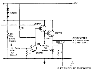
Car Alarm Sound Booster
Simple Car Alarm Sound Booster Circuit Diagram


 |
| Fig: Ultrasonic mosquito repeller circuit diagram |


 |
| Fig-1: 12V to 5V dc-dc converter circuit diagram |


 |
| Showing input value of 12V to 5V dc-dc converter circuit diagram |
 |
| Showing output value of 12V to 5V dc-dc converter circuit diagram |


 |
| DTMF Proximity Detector Circuit Diagram |
 |
| 1999-2000 Porsche 911 Carrera Electrical Wiring Diagram |
An amplifier to drive low to medium impedance headphones built using discrete components.
Both halves of the circuit are identical. Both inputs have a dc path to ground via the input 47k control which should be a dual log type potentiometer. The balance control is a single 47k linear potentiometer, which at center adjustment prevents even attenuation to both left and right input signals. If the balance control is moved towards the left side, the left input track has less resistance than the right track and the left channel is reduced more than the right side and vice versa. The preceding 10k resitors ensure that neither input can be "shorted" to earth.
Circuit diagram:
Headphone Amplifier Circuit Diagram
Amplification of the audio signal is provided by a single stage common emitter amplifier and then via a direct coupled emitter follower. Overall gain is less than 10 but the final emitter follower stage will directly drive 8 ohm headphones. Higher impedance headphones will work equally well. Note the final 2k2 resistor at each output. This removes the dc potential from the 2200u coupling capacitors and prevents any "thump" being heard when headphones are plugged in. The circuit is self biasing and designed to work with any power supply from 6 to 20 Volts DC.
Source : www.extremecircuits.net
 The state of the counter is decoded to produce the conditions listed in Table 2. Since it must be possible to reverse the direction of the current in the winding, each winding must be wired into a bridge circuit. This means that four transistors must be driven for each winding. Only diagonally opposed transistors may be switched on at any given time, since otherwise short circuits would occur. At first glance, Table 2 appears incorrect, since there seem to always be four active intervals. However, you should consider that a current flows only when a and c are both active. The proper signals are generated by the logic circuitry, and each winding can be driven by a bridge circuit consisting of four BC517 transistors.
 Two bridge circuits are needed, one for each winding. The disadvantage of this arrangement is that there is a large voltage drop across the upper transistors in particular (which are Darlingtons in this case). This means that there is not much voltage left for the winding, especially with a 5-V supply. It is thus better to use a different type of bridge circuit, with PNP transistors in the upper arms. This of course means that the drive signals for the upper transistors must be reversed. We thus need an inverted signal in place of 1a. Fortunately, this is available in the form of 1d.
 The same situation applies to 1b (1c), 2a (2d) and 2b (2c). In this case, IC4 is not necessary. Stepper motors are often made to work with 12V. The logic ICs can handle voltages up to 15 to 18 V, so that using a supply voltage of 12 V or a bit higher will not cause any problems. With a supply voltage at this level, the losses in the bridge circuits are also not as significant. However, you should increase the resistor values (to 22 kΩ, for example). You should preferably use the same power supply for the motor and the controller logic. This is because all branches of the bridge circuit will conduct at the same time in the absence of control signals, which yields short-circuits.
 Resistor R3 ensures that the regulation remains stable. The circuit can regulate ±2mA without any difficulties. Because of the low current drawn by IC1, and the high resistance of R1 and R2, the overall current drain is low. In the absence of a load, it was 13µA in the prototype, of which 1.5µA flows through R1-R2. Finally, since IC1 can operate from a voltage as low as 1.6V, the splitter will remain fully operational when the battery nears the end of its charge or life.
My current vehicle, a Pajero, was modified for dual fuel - ie, petrol and gas. However, its necessary to run the vehicle on petrol at regular intervals to stop the injectors from clogging up. This simple circuit allows the vehicle to be started using petrol and then automatically switches it to gas when the speed exceeds 45km/h and the brake pedal is pressed. Alternatively, the vehicle may be run on petrol simply by switching the existing petrol/gas switch to petrol. You can also start the vehicle on gas by pressing the brake pedal while starting the vehicle. The circuit is based on an LM324 dual op amp, with both op amps wired as comparators. It works like this: IC1a buffers the signal from the vehicles speed sensor and drives an output filter network (D1, a 560kO resistor and a 10µF capacitor) to produce a DC voltage thats proportional to the vehicles speed.
Circuit diagram:
This voltage is then applied to pin 5 of IC1b and compared with the voltage set by trimpot VR1. When pin 7 of IC1b goes high, transistor Q1 turns on. This also turns on transistor Q2 when the brake pedal is pressed (pressing the brake pedal applies +12V from the brake light circuit to Q2s emitter). And when Q2 turns on, relay 1 turns on and its contacts switch to the gas position. Trimpot VR1 must be adjusted so that IC1bs pin 7 output switches high when the desired trigger speed is reached (ie, 45km/h). In effect, the speed signal is ANDed with the brake light signal to turn on the relay. The vehicle has been running this circuit for several years now and is still running well, with no further injector cleans required.
Author: J. Malnar - Copyright: Silicon Chip Electronics
Source : www.extremecircuits.net
Copyright © Diagram Plus guide. All rights reserved.