Schematic | Circuit guide | Manual Wiring diagram | Electronic

Electronic Fuse Employs A Relay

Posted by Unknown Tuesday, April 30, 2013 0 comments
while many power supplies can be set to limit their output current to a defined level, to protect the circuit they are powering, no such protection is available if you are powering a circuit from a battery. If a fault develops, the circuit can blow before you have a chance to disconnect it. Of course, you can fit a fuse in series with the supply line to the circuit under test but it will blow if a fault develops. Or perhaps it won’t blow sufficiently quickly to protect the circuit. And repeatedly having to replace fuses becomes a nuisance as well.

Electronic Fuse Employs A Relay
The alternative is to use an electronic fuse. This circuit uses a relay to make and break the circuit. The current drain of the circuit under test is monitored by a 1O 2W resistor which is placed in series with the supply line. The voltage across this 1O resistor is monitored by op amp IC1a which has an adjustable gain of between 11 and 16, as set by trimpot VR1. The resultant DC voltage from pin 1 of IC1a is fed to pin 5 of IC1b which is configured as a comparator. Trimpot VR2 provides an adjustable voltage reference to pin 6 of IC1b and this is compared with the amplified signal from IC1a.

If IC1b’s threshold is exceeded, its pin 7 goes high and this is fed to Schmitt trigger inverter IC2a which then “sets” the RS flipflop comprising gates IC2c & IC2d. Pin 11 of IC2d then goes high to turn on transistor Q2 and LED1 while pin 4 of IC2b also goes high to turn on Q1 and the relay which then disconnects the load. The circuit stays in this state until the RS flipflop is reset by pushing switch S1. Capacitor Cx, across the feedback resistance of IC1a, is used to simulate a slow-blow or fast-blow fuse and can be selected by trial and error. Changing the gain of IC1a or the value of the sensing resistor changes the fuse rating of the circuit.

Simple Flashing Lights Schematic

Posted by Unknown Friday, April 26, 2013 0 comments
This is a straightforward flashing milds circuit can be used as beacon. The meeting consists basically of two blinking steps that commands two mild bulbs. With the lend a hand of P1 that you might be ready to adjust the flashing frequency between some restricts. There are 2 phases for the circuit, the 2d works the comparable manner as the opposite but with the lend a hand of a wire bridge or a switch that you could select different working modes.A bridge between M and three means: 2 unbiased blinks.

Circuit diagram :
Flashing Lights Schematic-Circuit Diagram

Flashing Lights Schematic Circuit Diagram

If there is a bridge between M and 2, then the lamps gentles alternatively with a frequency that can be modifyed with P1. And at last there may just be one extra possibility for M and 1, where the lamps blinks at the related time. The flashing milds circuit works with voltages between 3V and 15V. The lamps voltage have to be 2/3 of working voltage. R5 and R10 are chosen so that the lamps are about to light.

Simple Purpose Alarm

Posted by Unknown Sunday, April 21, 2013 0 comments
The alarm may be used for a variety of applications, such as frost monitor, room temperature monitor, and so on. In the quiescent state, the circuit draws a current of only a few microamperes, so that, in theory at least, a 9 V dry battery (PP3, 6AM6, MN1604, 6LR61) should last for up to ten years. Such a tiny current is not possible when ICs are used, and the circuit is therefore a discrete design. Every four seconds a measuring bridge, which actuates a Schmitt trigger, is switched on for 150 ms by a clock generator. In that period of 150 ms, the resistance of an NTC thermistor, R11, is compared with that of a fixed resistor. If the former is less than the latter, the alarm is set off.

When the circuit is switched on, capacitor C1 is not charged and transistors T1–T3 are off. After switch-on, C1 is charged gradually via R1, R7, and R8, until the base voltage of T1 exceeds the threshold bias. Transistor T1 then comes on and causes T2 and T3 to conduct also. Thereupon, C1 is charged via current source T1-T2-D1, until the current from the source becomes smaller than that flowing through R3 and T3 (about 3 µA). This results in T1 switching off, so that, owing to the coupling with C1, the entire circuit is disabled. Capacitor C1 is (almost) fully charged, so that the anode potential of D1 drops well below 0 V. Only when C1 is charged again can a new cycle begin.


It is obvious that the larger part of the current is used for charging C1. Gate IC1a functions as impedance inverter and feedback stage, and regularly switches on measurement bridge R9–R12-C2-P1 briefly. The bridge is terminated in a differential amplifier, which, in spite of the tiny current (and the consequent small transconductance of the transistors) provides a large amplification and, therefore, a high sensitivity. Resistors R13 and R15 provide through a kind of hysteresis a Schmitt trigger input for the differential amplifier, which results in unambiguous and fast measurement results. Capacitor C2 compensates for the capacitive effect of long cables between sensor and circuit and so prevents false alarms.

If the sensor (R11) is built in the same enclosure as the remainder of the circuit (as, for instance, in a room temperature monitor), C2 and R13 may be omitted. In that case,C3 willabsorb any interference signals and so prevent false alarms. To prevent any residual charge in C3 causing a false alarm when the bridge is in equilibrium, the capacitor is discharged rapidly via D2 when this happens. Gates IC1c and IC1d form an oscillator to drive the buzzer (an a.c. type). Owing to the very high impedance of the clock, an epoxy resin (not pertinax) board must be used for building the alarm. For the same reason, C1 should be a type with very low leakage current. If operation of the alarm is required when the resistance of R11 is higher than that of the fixed resistor, reverse the connections of the elements of the bridge and thus effectively the inverting and non-inverting inputs of the differential amplifier.

An NTC thermistor such as R11 has a resistance at –18 °C that is about ten times as high as that at room temperature. It is, therefore, advisable, if not a must, when precise operation is required, to consult the data sheet of the device or take a number of test readings. For the present circuit, the resistance at –18 °C must be 300–400 kΩ. The value of R12 should be the same. Preset P1 provides fine adjustment of the response threshold. Note that although the prototype uses an NTC thermistor, a different kind of sensor may also be used, provided its electrical specification is known and suits the present circuit.


Author: K. Syttkus
Copyright: Elektor Electronics


Soldering Iron Tip Preserver

Posted by Unknown 0 comments
Although 60/40 solder softens at about 200°C, the tip temperature of a soldering iron must be at about three70°C. This is important to make a just right fast joint, without the danger of overheating refined parts because the iron needs to be saved on the joint for too long. Unfortunately, at this temperature, the tip oxidises swiftly and needs constant cleaning. Thats the place this circuit can help - it preserves the soldering tip to simplest beneath 200°C while the iron is at leisure. Oxidisation is then negligible and the iron will additionally be introduced again up to soldering temperature in just a few seconds when needed. In addition, standard soldering operation, where the iron is returned to leisure only momentarily, is unaffected on account of the thermal inertia of the iron. Two 555 timers (IC1 & IC2) type the heart of the circuit. 

Circuit diagram:
soldering-iron-tip-preserver circuit diagram
Soldering Iron Tip Preserver Circuit Diagram

IC1 is wired as a monostable and provides an initial warm-up time of about 45 2nds to deliver the iron as much as temperature. At the end of this era, its pin three output switches high and IC2 (which is wired in astable configuration) switches the iron on - by means of relay RLY1 - for approximately one second in six to care for the standby temperature. The presence of the iron in its stand is sensed via electrical contact between the 2 and some slight modification of the stand may be important to be successful in this. When the iron is at relaxation, Q1s base is pulled low and so Q1 is off. Conversely, when the iron is out of its stand, Q1 turns on and pulls pins 2 & 6 of IC2 high, to inhibit its operation. During this time, pin 3 of IC2 is low and so the iron is constantly powered by the use of RLY1s normally closed (NC) contacts. Note that the particular soldering iron that the circuit was once designed for has its personal 24V supply transformer. Other irons might want different energy provide associations. The warm-up time and standby temperature may additionally be diversified by way of altering R2 and R5, as essential.


Author: Alan March - Copyright: Silicon Chip Electronics

Digital Bike Tachometer SP

Posted by Unknown Saturday, April 13, 2013 0 comments
This digital SP tachometer for bikes uses 2 reed switches to urge the speed data of the bicycle. The reed switches are put in close to the rim of the wheel where permanent magnets pass by. The permanent magnets are connected to the wheelspokes and activate the reed switches everytime they pass by it. The speed is digitally displayed.

The tachometer circuit works in step with this principle; the pulses created by the reed contacts are counted inside an explicit time interval. The ensuing count is then displayed and represents the speed of the bike. 2 4026 ICs are used to count the pulses, decode the counter and management 2 7-segment LED show. RS flip-flops U3 and U4 perform as anti-bounce.

Electronic bicycle SP tachometer circuit diagram


The pulses arrive at the counter’s input through gate U7. The measuring amount is set by monostable multivibrator U5/U6 and might be adjusted through potentiometer P1 so the tacho are often calibrated. The circuit U1/U2 resets the counters.

Since batteries are used to power the circuit, its not sensible to support the continual show of speed data. This circuit isnt continuously active. The circuit is activated solely once a button is pressed. a minimum of 3 permanent magnets should be put in on the wheel. The circuit are often calibrated with the assistance of another pre-calibrated tachometer.


Streampowers

Build 20W MOSFET Power Amplifier Circuit with IFR9520 IFR520

Posted by Unknown 0 comments
As we are like to indicate you about audio and sound circuit ,I found the circuit which is just right one for energy amplifier with one MOSFET.

The output power of an operational amplifier is regularly elevated by way of a complementary emiter follower.


20W energy amp MOSFET

It can be carried out with a MOSFET,but it's not a excellent suggestion to join the type of instrument as a complementary souce follower because the maximum output voltage of the opamp is then decreased extensively by way of the gate-source keep a watch on voltage of the MOSFET ,which can be a few volts.

Another method is to join two MOSFETs as a complementary drain follower.The (alternating) output current provided by using the MOSFETs is limited by way of the stage of the provision voltages and the saturateion voltages of T3 and T4 Resistor R8,together with R9,provides comments for each the opamp and MOSFETs .

The open-loop amplification of the opampis,therefore,increased via (1+R8/R9).the closed-loop amplification of the entire amplifier is (1+R3/R2).

The present source shaped by using T1 and T2 is required for arreanging the quiescent present of T3 and T4 at 50 mA.The values of resistors R4 and R5 are such that,without the present supply the voltage drop throughout the resistor because of the direct present in the route of the opamp is not enough to change on T3 and T4 .with the present supply,and depending on the surroundings of P1,the voltages across R4 and R5 upward push,which increases the quiescent present by means of T3 and T4.

In view of the temperature dependence of the quiescent present,T2 must be hooked up on the popular heat sink(c. 5 K/W) of the MOSFETs.

The output power shouldn't be less than 20 W into 8 ohm,at which level the harmonic distortion quantitys to zero.075 per cent at one hundred Hz to zero,135 per cent at 10 kHz.

CONSTANT BRIGNESS LED AND MUTE CONTROL ELECTRONIC DIAGRAM

Posted by Unknown 0 comments

CONSTANT BRIGNESS LED AND MUTE CONTROL ELECTRONIC DIAGRAM

The output power of the modules are approximately 220W to 250W into 8? and 350W to 400W into 4?. Complete documentation for the amplifier modules can be found in the documents listed below. AN-1850 LME49830TB Ultra-High Fidelity, High-Power Amplifier Reference Design Although the power supply design is specific to the amplifier modules the concepts and circuit design may be used for any power supply purpose. The power supply is an unregulated design with an option to allow connection to either 120V or 240V mains. The design uses toroidal transformers, a fully integrated bridge, and various rail capacitors for ripple voltage reduction, noise suppression, and to act as high current reservoirs. Additional circuitry to control inrush current on power up and power up/ down Mute control are also included.

The topics discussed inside the application note including the introduction, overview, schematic and design, power supply, additional circuit, inrush current control, mute control, constant brightness LED circuit, summary, and many more.

Cheap Bicycle Alarm Schematics Circuit

Posted by Unknown 0 comments
The author wanted a very cheap and simple alarm for some of his possessions, such as his electrically assisted bicycle. This alarm is based on a cheap window alarm, which has a time-switch added to it with a 1-minute time-out. The output  pulse of the 555 replaces the reed switch in the window alarm. The 555 is triggered by a sensor mounted near the front  wheel, in combination with a magnet that is mounted on the spokes. This sensor and the magnet were taken from a cheap bicycle computer. 

Circuit diagram :
Cheap Bicycle Alarm-Circuit Diagram
Cheap Bicycle Alarm Circuit Diagram

The front wheel of the bicycle is kept unlocked, so that the reed  switch closes momentarily when the wheel turns. This  triggers the 555, which in turn activates the window alarm. The circuit around the 555 takes very little current and can  be powered by the batteries in the window alarm.  There  is just enough room  left inside the enclosure of the window  alarm to mount the time-switch inside it. 

The result is a very cheap, compact device, with only a single cable going to the reed switch on the front wheel. And the noise this thing produces is just unbelievable! After about one minute the noise stops and the alarm goes back into standby mode. The bicycle alarm should be mounted in an inconspicuous place, such as underneath the saddle, inside a (large) front light, in the battery compartment, etc.
Hopefully the alarm scares any potential thief away, or at least it makes other members of the public aware that something isnt quite right. 

Caution. The installation and use of this circuit may be subject to legal restrictions in your country, state or area.
 
http://streampowers.blogspot.com/2012/07/cheap-bicycle-alarm-schematics-circuit_06.html 

Mains Pulser

Posted by Unknown Friday, April 12, 2013 0 comments
The pulser is intended to change the primarys voltage on and off at intervals between just below a 2d and as a lot as 10 minutes. This comes in handy, for instance, when a chiefs-operated gear is to be tested for lengthy periods, or for lengthic switching of equipment. Transformer Tr1, the bridge rectifier , and regulator IC1 present a stable 12V provide rail for IC2 and the relay. The timer is arranged so that the length-determining capacitor may additionally be charged and discharged independently. Four time ranges can additionally be chosen by means of deciding on capacitors with assistance from jumpers. Short-circuiting positions 1 and 2 offers the lengthyest time, and short-circuiting none the shortest.

Circuit diagram:
Mains Pulser Circuit Diagram

In the latter case, the 10µF capacitor at pins 2 and 6 of the timer IC determines the time with the relevant resistors. The value of this capacitor could also be chosen rather lower. The two preset potentiometers permit the on and off durations to be set. The 1k resistor in series with one of the crucial presets resolves the minimal discharge time. The timer IC switches a relay whose double-pole contacts swap the mains voltage. The LEDs point out whether the mains voltage is switched through (red) or no lengthyer (green). The 100mA slow fuse give safety tos the principles transformer and low-voltage circuit. The 4 A medium sluggish fuse give protection tos the relay once morest overload.

Source : extremecircuits.net

12 V – 15A Voltage Regulator Circuit

Posted by Unknown 0 comments
This is a circuit diagram of a powerful 12V regulator. The circuit can deliver up to 15 A of current. The circuit is based on work of the LM7812 IC as the core of the circuit. This is the figure of the circuit.


The common voltage regulator IC 7812(IC1) is used to keep the voltage at steady 12V and three TIP 2599 power transistors in parallel are wired in series pass mode to boost the output current.

The operation work of the circuit is the 7812 can provide only up to 1A and rest of the current is supplied by the series pass transistors. The 15A bridge B1 does the job of rectifying the stepped down AC input. The capacitor C1, C2 and C3 act as filters. The 1A fuse F1 protects the IC1 from over current in case if the pass transistors fail. The 15A fuse F2 protects the entire circuit (especially the pass transistors) from over current. The T1 can be a 230V AC primary, 18V secondary, 15A type transformer. The B1 can be a 15A bridge. If 15A Bridge is not available, make one using four RURG1520CC diodes. The IC1 and transistors must be mounted on heat sinks.

1998 Isuzu Rodeo 3 2 6 cyl Wiring Diagram

Posted by Unknown 0 comments
1998 Isuzu Rodeo 3.2 6 cyl Wiring Diagram


The Part of 1998 Isuzu Rodeo 3.2 6 cyl Wiring Diagram: red wire, coil contact, headlight relay,
connector, relay ctrl, fuse box, rear wipper, starter, theft horn, black wire, horn, hazard

Car Reversing Horn with Flasher

Posted by Unknown 0 comments
Here is a simple circuit that starts playing the car horn whenever your car is in reverse gear. The circuit (refer Fig. 1) employs dual timer NE556 to generate the sound. One of the timers is wired as an astable multivibrator to generate the tone and the other is wired as a monostable multivibrator.

Circuit diagram :
 Simple Car-Reversing Horn with Flasher- Circuit Daigram

Fig. 1: Car reverse horn Circuit Diagram

Working of the circuit is simple. When the car is in reverse gear, reverse-gear switch S1 of the car gets shorted and the monostable timer triggers to give a high output. As a result, the junction of diodes D1 and D2 goes high for a few seconds depending on the time period developed through resistor R4 and capacitor C4. At this point, the astable multivibrator is enabled to start oscillating. The output of the astable multivibrator is fed to the speaker through capacitor C6. The speaker, in turn, produces sound until the output of the monostable is high.

When the junction of diodes D1 and D2 is low, the astable multivibrator is disabled to stop oscillating. The output of the astable multivibrator is fed to the speaker through capacitor C6. The speaker, in turn, does not produce sound.

Assemble the circuit on a general-purpose PCB and enclose in a suitable cabinet. Connect the circuit to the car reverse switch through two wires such that S1 shorts when the car gear is reversed and is open otherwise. To power the circuit, use the car battery.

The flasher circuit (shown in Fig. 2) is built around timer NE555, which is wired as an astable multivibrator that outputs square wave at its pin 3. A 10W auto bulb is used for flasher. The flashing rate of the bulb is decided by preset VR1.

Flasher-circuit diagram

Fig. 2: Flasher Circuit Diagram

Assemble the circuit on a general-purpose PCB and enclose in a suitable cabinet. The flasher bulb can be mounted at the cars rear side in a reflector or a narrow painted suitable enclosure.

EFY note. A higher-wattage bulb may reduce the intensity of the headlight. You can enclose both the car-reversing horn and flasher circuits together or separately in a cabinet in your car.

Source :  http://www.ecircuitslab.com/2011/06/car-reversing-horn-with-flasher.html

Universal PIC Programmer Circuit

Posted by Unknown 0 comments
Universal PIC Programmer Circuit
The series of Universal PIC Programmer can be used with software IC-Prog 1:05. Universal PIC programmer circuit is very simple with BC337 transistor 1 fruit, 2 pieces of IC regulators 7805 and 7808 as well as supporting passive components. Universal PIC Programmer series can be supplied with 2 pieces of 9V batteries.

For communication with computer circuit Universal PIC Programmer uses a serial RS232 port of computer. Then for the PIC to be programmed provided 5 lanes for the PIC that is DATA, Clock, Vpp, Vcc and Ground. For more details, can be directly seen in the figure below.

Universal PIC Programmer Circuit diaggram
Universal PIC programmer circuit diagram

The series of Universal PIC Programmer can be used to program the PIC family of 16F84A series, 12C509, 16C765 and the other. Hopefully this series of Universal PIC Programmer can help for friends who want to make PIC programmer.

Simple Lighting Surge Protector Circuit

Posted by Unknown Thursday, April 11, 2013 0 comments
GDT’s are special type of gas filled tubes used for wide range of electronic/electrical circuits for providing protection against lightning and other power surges.  These tubes basically has two electrodes that are kept inside a gas filled closed envelope. In case of electronic applications, the container is mostly ceramic in nature. For high grade electrical applications military tubes are used. The electrical characteristics of this tubes depends on the pressure and composition of gas, and the distance between the two electrodes contained inside. The most commonly used gases in GDT’s are given below.

1) Hydrogen gases
2) Deuterium gases
3) Noble gases
4) Elemental vapors (metals and nonmetals)
5) Other gases
6) Insulating gases
An image of a ceramic discharge tube is shown below. Take a look.

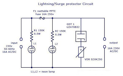
There will be conduction inside the GDT’s due to ionization of gas molecules. Each GDT have a specific voltage and current rating. A simple lightning protector circuit is given below.

Lighting/Surge Protector Circuit

In power lines, usually large amount of voltage is induced (typically very short time with high amplitude) due to lightning (direct or indirect strike) or Transients*
* (Transients caused by other equipments are usually caused by the discharge of stored energy in inductive and capacitive components. Electric motors, such as those used in elevators, heating, air conditioning, refrigeration or other inductive loads, can create a continuous stream of 250V to 1000V transients. DC motor drives, variable speed AC motor drives, DC power supply switching, and portable power tools are other sources of transients.)

Lightning protection circuit:

Simple Lighting Surge Protector Circuit

The basic surge suppression circuit shown below consists of a VDR** (Voltage Dependent Resistor) and gas surge suppressor (GDT) connected in series. The protection circuit is connected between live and mains lead. Normally no current flows through GDT and VDR1. When   the voltage between the terminals is higher than the sum of voltage ratings of GDT and VDR1 (here both GDT UZ470B and VDR S20K250 has 250v 16A rating), current starts to flow through those components. 

If more the voltage rises then more current starts to flow through GDT and VDR1.When the current is normal, the circuit is reset and resumes it’s functioning. Thus the current cannot be raised much over that predetermined value. When the voltage again goes back to normal values G1 and VDR1, the conducting stops and the circuit remains normal.  If the flowing current is more than the specified value of main self-resettable fuse, the fuse will break and the circuit will be protected. After the current is normal, the fuses resets and continue its functioning (protection against short circuit and overload). 

The circuit is designed to protect sensitive electronic devices against overvoltage transients in normal mains voltage and overload/ short circuit. Two neon pilot lamps are also provided with the circuit diagram to show the status of input and load supply.

(**A VDR (Voltage Dependent Resistor) is an electronic component with a “diode-like” nonlinear current–voltage characteristic. The name is a portmanteau of variable resistor.  VDRs are often used to protect circuits against excessive transient voltages by incorporating them into the circuit in such a way that, when triggered, they will shunt the current created by the high voltage away from the sensitive components. A VDR is also known as Voltage Dependent Resistor or VDR. A VDR’s function is to conduct significantly increased current when voltage is excessive.)

Voltage Dependent Resistor

Advantages:

1)      Normal working voltage = 230v AC/DC
2)      Maximum current rating=16A
3)      Cut-off current =16A
4)      Cut-off voltage= >300v R.M.S
5)      Protection against overloads
6)      Protection for short circuit

Applications:

1)      Protection for sensitive components
2)      Protection for motor devices
3)      Telephone line protection
4)      SMPS protection

1994 Chevrolet S10 Blazer Wiring Diagram

Posted by Unknown 0 comments
1994 Chevrolet S10 Blazer
(click for full size image)

The Part of 1994 Chevrolet S10 Blazer Wiring Diagram: shunt, fuse block, rear defogger, engine ground, indicator, rear window strut, panel lamps, circuit breaker.

Long Interval Pulse Generator

Posted by Unknown 0 comments
A rectangular-wave pulse generator with an extremely long period can be built using only two components: a National Semiconductor LM3710 supervisor IC and a 100-nF capacitor to eliminate noise spikes. This circuit utilises the watchdog and reset timers in the LM3710. The watchdog timer is reset when an edge appears on the WDI input (pin 4). If WDI is continuously held at ground level, there are not any edges and the watchdog times out. After an interval TB, it triggers a reset pulse with a duration TA and is reloaded with its initial value. The cycle then starts all over again. As a result, pulses with a period of TA + TB are present at the RESET output (pin 10).

Circuit diagram:
long-interval-pulse-generator-circuit-diagram Long-Interval Pulse Generator Circuit Diagram

long-interval-pulse-generator-diagram

As can be seen from the table, periods ranging up to around 30 seconds can be achieved in this manner. The two intervals TA and TB are determined by internal timers in the IC, which is available in various versions with four different ranges for each timer. To obtain the desired period, you must order the appropriate version of the LM3710. The type designation is decoded in the accompanying table. 

The reset threshold voltage is irrelevant for this particular application of the LM3710. The versions shown in bold face were available at the time of printing. Current information can be found on the manufacturer’s home page (www.national.com). The numbers in brackets indicate the minimum and maximum values of intervals TA and TB for which the LM3710 is tested. The circuit operates with a supply voltage in the range of 3–5 V.
Source by : Streampowers

Contrast Control for LCDs

Posted by Unknown 0 comments
The adjustment control for the contrast of an LC-Display is typically a 10-k potentiometer. This works fine, provided that the power supply voltage is constant. If this is not the case (for example, with a battery power supply) then the potentiometer has to be repeatedly adjusted. Very awkward, in other words. The circuit described here offers a solution for this problem. 

The aforementioned potentiometer is intended to maintain a constant current from the contrast connection (usually pin 3 or Vo) to ground. A popular green display with 2x16 characters ‘supplies’ about 200 µA. At a power supply voltage of 5 V there is also an additional current of 500 µA in the potentiometer itself. Not very energy efficient either. Now there is an IC, the LM334, which, with the aid of one resistor, can be made into a constant current source. The circuit presented here ensures that there is a current of 200 µA to ground, independent of the power supply voltage. By substituting a 2.2-k? potentiometer for R1, the current can be adjusted as desired.

Circuit diagram:The value of R1 can be calculated as follows: R1 = 227x10-6 x T / I. Where T is the temperature in Kelvin and I is the current in ampères. In our case this results in:
R1 = 227x10-6 x 293 /
(200x10-6)
R1 = 333R

Note that the current supplied by the LM334 depends on the temperature. This is also true for the current from the display, but it is not strictly necessary to have a linear relationship between these two. Temperature variations of up to 10° will not be a problem however. This circuit results in a power saving of over 25% with an LCD that itself draws a current of 1.2 mA. In a battery powered application this is definitely worth the effort! In addition, the contrast does not need to be adjusted as the battery voltage reduces. When used with LCDs with new technologies such as OLED and PLED it is advisable to carefully test the circuit first to determine if it can be used to adjust the brightness.

Circuit diagram:
contrast-control-for-lcd-circuit-diagramw
Contrast Controller Circuit Diagram For LCDs

The value of R1 can be calculated as follows: R1 = 227x10-6 x T / I. Where T is the temperature in Kelvin and I is the current in ampères. In our case this results in:
  • R1 = 227x10-6 x 293 /
  • (200x10-6)
  • R1 = 333R
Note:
  • The current supplied by the LM334 depends on the temperature. This is also true for the current from the display, but it is not strictly necessary to have a linear relationship between these two. Temperature variations of up to 10° will not be a problem however. This circuit results in a power saving of over 25% with an LCD that itself draws a current of 1.2 mA. In a battery powered application this is definitely worth the effort! In addition, the contrast does not need to be adjusted as the battery voltage reduces. When used with LCDs with new technologies such as OLED and PLED it is advisable to carefully test the circuit first to determine if it can be used to adjust the brightness.
     
     
    http://www.ecircuitslab.com

TV Vertical Protectors

Posted by Unknown 0 comments
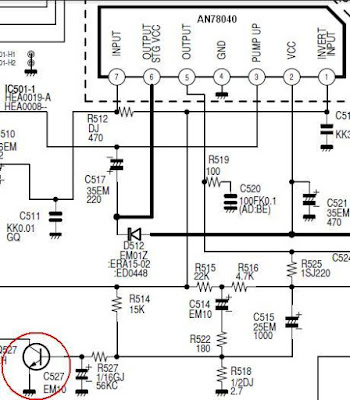
Vertical Protectors (another term surge protector or Vertical CRT Neck Guard or protector) . If the vertical deflection does not work, then the raster will glow a horizontal line. This can cause the picture tube phosphor layer was destroyed by fire when the aircraft be kept alive in the long term.

There are several types of system protectors, vertical relationships:
  • Protector surge protector is connected with x-ray to the horizontal which will trigger the horizontal oscillator is not working
  • Protectors gets connected to microcontrol that will trigger the "power off" so that the plane will turn off automatically or plane alive but raster becomes dark (brightnes level down).
TV Vertical Protectors
Vertical Protect
The workings of the system-vertical surge protector that can be found there are several kinds:

  • Using sampling pulses from vertical-out IC which is connected to microcontrol . If microcontrol  not receive these pulses the surge protector will work.
  • Using a sampling of the voltage supply Vcc-vertical IC connected to the IC microcontrol  using a diode. In the normal kondidi no voltage on the pin-IC microcontrol  protection. If the supply voltage Vcc or a short break then the voltage on the pin-microcontrol protection will come short to ground through the diode and trigger protection to actively work
  • Using the IC supply current sampling vertical-out that will actively work if the current exceeds supply. As the sensor protector installed here a series resistor and a transistor in the supply line where it works similar to the OCP.
Problems or possibilities that may cause the protector of vertically-active work:
  • Vertical IC-out short (broken)
  • No voltage supply to the vertical IC-out.
  • Vertical lines of the IC pulse-out to any part microcontrol  broken or damaged
  • Vertical deflection section does not work (damage to the IC)


Video Isolator

Posted by Unknown Wednesday, April 10, 2013 0 comments
These days many more audio-visual devices in the home are connected together. This is especially the case with the TV, which may be connected to a DVD player, a hard disk recorder, a surround-sound receiver and often a PC as well. This often creates a problem when earth loops are created in the shielding of the video cables, which may cause hum and other interference. The surround-sound receiver contains a tuner that takes its signal from a central aerial distribution system. The TV is also connected to this and it’s highly likely that the PC has a TV-card, which again is connected to the same system. On top of this, there are many analogue connections between these devices, such as audio cables. The usual result of this is that there will be a hum in the audio installation, but in some cases you may also see interference on the TV screen.

The ground loop problem can be overcome by galvanically isolating the video connections, for example at the aerial inputs of the surround-sound receiver and the TV. Special adaptors or filters are sold for this purpose, known as video ground loop isolators. Good news: such a filter can also be easily made at home by yourself. There are two ways in which you can create galvanic isolation in a TV cable. The first is to use an isolating transformer with two separate windings. The other is to use two coupling capacitors in series with the cable. The latter method is easily the simplest to implement and generally works well enough in practice. The simplest way to produce such a ‘filter’ is as an in-line adapter, so you can just plug it onto either end of a TV aerial cable.

Video Isolator Circuit diagram:


The only requirements are a male and female coax plug and two capacitors. The latter have to be suitable for high-frequency applications, such as ceramic or MKT types. It is furthermore advisable to choose types rated for high voltages (400 V), since the voltages across these capacitors can be higher than you might expect (A PC that isn’t connected to the mains Earth can have a voltage as high as 115 V (but at a very low, safe current), caused by the filter capacitors in its power supply. These capacitors don’t need to be high value ones, since they only have to pass through frequencies above about 50 MHz. Values of 1 nF or 2.2 nF are therefore sufficient. To make the isolator you should connect one capacitor between the two earth connections of the coax plugs and the other between the two signal connections.

The mechanical construction has to be sturdy enough such that the connections to the capacitors won’t break whenever the inline adapter is removed forcibly. A good way to do this is to make a cover from a piece of PVC piping for the central part. Wrap aluminium foil round the outside and connect it to one of the plugs, so that the internal parts are properly shielded from external interference. Make sure that the aluminium foil doesn’t make contact with the other plug, otherwise you lose the isolation. The majority of earth loops will disappear when you connect these filters to all used outputs of the central aerial distribution system where the signal enters the house.
Harry Baggen
 
Copyright : Elektor Electronics 2008

Source:http://www.ecircuitslab.com/2011/07/video-isolator-circuit-diagram.html

Preamplifier For Soundcard

Posted by Unknown 0 comments
This circuit can be used for inductive pick-up elements and dynamic microphones Most soundcards have a ‘line’ input and one for an electret (condenser) microphone. To be able to connect an inductive tape-recorder head or a dynamic microphone, an add-on preamplifier is needed. Even in this day and age of integrated microelectronics, a transistorised circuit built from discrete part has a right of existence. The preamplifier described in this short article goes to show that it will be some time before discrete transistors are part of the silicon heritage. The preamplifier is suitable for use with a soundcard or the microphone input of a modem. As you will probably know, most sound-cards have input sockets for signals at line level (stereo), as well as one for a (mono) electret microphone.

For the applications we have in mind, connecting-up an inductive pick-up element or a dynamic microphone, both inputs are in principle suitable, provided the source signal is amplified as required. The author eventually chose the microphone input on the soundcard. Firstly, because the line inputs are usually occupied, and secondly, because the bias voltage supplied by the micro-phone input eliminates a separate power supply for the preamplifier. The microphone input of a soundcard will typically consist of a 3.5-mm jack socket in stereo version, although only one channel is available. The free contact is used by the soundcard to supply a bias voltage to the mono electret microphone. This voltage is accepted with thanks by the present preamplifier, and conveniently obviates an external (mains adaptor) power supply.

Preamplifier For Soundcard Circuit diagram:


A classic design:
In true transistor-design fashion, the preamplifier consists of three stages. Capacitor C1 decouples the signal received from the microphone or pick-up element, and feeds it to the input of the first stage, a transistor in emitter configuration, biased to provide a current amplification of about 300 times. Together with the source impedance of the microphone or pick-up element, capacitors C2 and C3 form a low-pass filter which lightly reduces the bandwidth. In addition, the output low-pass, R2-C3, reduces the dynamic collector resistance at higher frequencies. In this way, the filter reduces the gain in the higher part of the frequency spectrum and so helps to eliminate any oscillation tendencies.

The first, high-gain, stage is terminated by T2. Unlike T1, this transistor does not add to the overall gain, because the output signal is taken from the emitter (common-collector circuit). T2 thus acts as an impedance converter, with C4 reducing any tendency to oscillation. The output stage around T3 is a common-emitter circuit again. In it, preset P1 determines the voltage amplification. T3 is biased by means of a direct-current feedback circuit based on components R7 and C5. To this is added an ‘overruling’ dc feedback path back to the input transistor, via R6. This measure guarantees good dc stability in the preamplifier. The circuit is small enough to be built on a piece of veroboard or stripboard, and yet remain reasonably compact.

To prevent interference from external sources, the completed board should be mounted in a properly screened (metal) enclosure, with the connections to the input source and the sound card made in screened cable. The preamplifier provides a frequency-linear response. In case the source signal is marked by frequency correction (e.g., RIAA), then a matching linearization circuit should be used if the relevant signals are used by the computer.

Source : http://www.ecircuitslab.com/2011/07/preamplifier-for-soundcard-circuit.html

Simple Clap Operated Stairway Light Switch Circuit

Posted by Unknown 0 comments
Stairways, corridors or small indoor passages often tend to be dark throughout the day irrespective of the outdoor ambient light conditions. Therefore keeping such passages illuminated all the the time becomes imperative, however this leads to unnecessary wastage of electricity.

 An innovative way of solving this problem has been discussed in this article, by employing a clap operated momentary light switch circuit.

The circuit diagram may be understood as follows:

The idea is to switch ON the connected lights in the corridor through a  clap sound, whenever the involved passage is utilized.
The clap sound triggers the circuit and keeps the connected lights switched ON for a few seconds or until the predetermined time is lapsed, after which the lights are automatically switched OFF.

The configuration is actually a transistor based clap switch, but without a flip flop stage, rather the flip flop is replaced by a delay OFF timer stage for the necessary switching and sustaining of the lights for a fixed predetermined period.
The stage as usual includes a sound sensor stage consisting of a mic and the subsequent transistor amplifier stage using a couple BC547 transistors.

The next stage consists of the PNP transistor BC557 which receives the signals amplified from the first stage via the 47uF capacitor.
The fed signals are further amplified to much greater levels for triggering the final LED driver stage.
The LED driver stage consists of a group of white LEDs which provides enough light for illuminating a small passage premise.
The two 39K resistors and the 220uF capacitors form the basic delay OFF timer and decides for how many seconds the driver stage remains ON with the LEDs lit.

The power to the circuit can be either applied by incorporating a standard transformer/bridge AC/DC adapter or if the circuit needs to be more compact, a transformerless power supply may be included with the below shown circuit.

All the NPN transistors are BC547B and the single PNP transistor is a BC557B, LEDs are ordinary 5mm high efficiency white LEDs.

The coil can be of any type, a 100mH choke will also do, its introduced in order to keep the circuit stable and for avoiding self oscillations.


Traffic Light Controller

Posted by Unknown 0 comments
Here the simple traffic light controller which is could be used to educate kids rudiments of traffic light guidelines. The circuit utilizes easily available electronic parts. It generally consists of rectifier diodes (1N4001), a 5V regulator 7805, two timers circuit using IC 555, two relays (5V, single-changeover), three 15W, 230V light bulbs and also several discrete parts.

Traffic Light Controller Circuit diagram :


Mains electrical power is stepped down by transformer X1 to provide a secondary output voltage of 9V, 300 mA – AC. Then the transformer output current is rectified by a full-wave bridge rectifier composed of diodes D1 through D4, filtered by capacitor C1 and also regulated by IC 7805 (IC1).

IC2 is wired as a multivibrator with ‘on’ and ‘off’ periods of about 30 seconds each with the part values determined. Once mains power switch is turned on, pin 3 of IC2 goes high for 30 seconds. This, in turn, energises relay RL1 via transistor T1 and the red bulb (B1) glows through its normally-open (N/O) contact. At the same time, mains power is turned off from the pole of relay RL2. As the ‘on’ time of IC2 ends, a triggers IC3 through C5. IC3 is set up as a monostable with ‘on’ time of about 4 seconds, which indicates pin 3 of IC3 will stay high for this period of time and energise relay RL2 through driver transistor T2. The amber bulb (B2) thus lightings up for 4 seconds.

Immediately after 4-second time period of timer IC3 at pin 3 lapses, relay RL2 de-energises and also the green bulb (B3) lights up for the rest of ‘off’ period of IC2, which is about 26 seconds. The green bulb is turned on through the normally closed (N/C) contacts of relay RL2. So when mains electrical switch is turned on, red light will light up for 30 seconds, amber for 4 seconds and green for 26 seconds.

You can easily build this circuit on a general purpose PCB and enclose in a protected box. The box needs to have sufficient area for installing transformer X1 and also two relays. It could be installed near 230V AC, 50Hz power supply or mounted on the PVC tube applied in assembly of the traffic light box.

Design of the traffic light container box is demonstrated in following image:


A stout cardboard box of 30x15x10cm3 is needed for housing the lights. To make certain durability, work with a 10x45cm2 plywood plate having 1.5 centimeters thickness and also secure onto it three light outlets and the box utilizing nuts and bolts or screws. Make three tubes of thin aluminium sheet, which is easily offered in equipment stores. The inner diameter of aluminium tubes ought to be such that these can well match on the light outlets. Working with a sharp knife, make holes opposite the outlets carefully. Wire the outlets at the back and take the cables out through the PVC tube.

To begin with, fix three 15W light bulbs (B1 through B3) and then press on the tubes. Support the other ends of the tubes in the holes made on the front panel of cardboard box. Sandwich gelatine papers of the three colors in between two sheets of cardboard and fix over the tubes. The visibility of red, amber and also green lights enhances with their installation on the tubular shape.

Current Limiter Circuit Using two transistors

Posted by Unknown 0 comments
In many critical applications, circuits are required to maintain a strict controlled magnitude of current through them of at their outputs. The proposed circuit is exactly meant for carrying out the discussed function. The lower transistor is the main output transistor which operates the output vulnerable load and by itself is unable to control the current through it.

The introduction of the upper transistor makes it sure that the base of the lower transistor is allowed to conduct as long as the current output is within the specified limits. In case the current tends to cross the limits, the upper transistor conducts and switches OFF the lower transistor inhibiting any further passage of the exceeded current limit. The threshold current may be fixed by R which is calculated with the shown formula.

2001 Chevrolet Malibu 3 1L Wiring Diagram

Posted by Unknown 0 comments
2001 Chevrolet Malibu 3.1L Wiring Diagram
(click for full size image)

The Part of 2001 Chevrolet Malibu 3.1L Wiring Diagram:
ctrl module, system schematics, red wire, throttle, refrigerant pressure, low reference, fuel pump, manifold absolute pressure, intake air temperature

Battery Discharge Monitor Using TL431

Posted by Unknown Tuesday, April 9, 2013 0 comments
This is a battery monitor circuit which disconnect the load when the battery is discharged, preventing a deep discharge which could cause permanent battery damage. The battery is automatically reconnected when a battery charger or other DC source is connected across the load. Select a relay which requires less than 100ma coil current and with contacts capable of handling the load and charging currents. This figure is about the circuit.


The principle work of the circuit is C1 should be about one hundred micro-farads and C2 may be near 1 micro-farad. C2 simply delays the closing of the relay long enough for C1 to charge and C1 keeps the relay closed long enough for the battery voltage to climb above the cut-off point (about 22 volts for the circuit as shown). The 210k resistor may be reduced to 92k for 12 volt batteries. These R1 values may be reduced if a lower drop-out voltage is desired. The circuit may cycle on and off several times if the battery is deeply discharged with a delay proportional to the value of C1. The load sees the full voltage of the charger before the relay connects the battery in this circuit and in some applications the version below may be more desirable.

2x70Watt Amplifier Circuit

Posted by Unknown 0 comments
Stereo Power Amplifier is 2x70Watt STA550 chip audio power with BASH concept that can be connected with digital perangkkat. 2x70Watt STA550 Stereo Power Amplifier is an amplifier with BTL system with symmetrical power supply with ground. Power amplifier STA550 uses power output transistor which is on the chip and is set to produce a high efficiency audio power.
Power output on the STA550 is using the system without copling ac bridge (direct) and zero offset. Strengthening of the STA550 from stereo power amplifier is +12 dB. 2x70Watt STA550 Stereo Power Amplifier is equipped with temperature sensors for protection from overheating and current-limiting protection system for power amplifier. 2x70Watt STA550 Stereo Power Amplifier is equipped with standby and mute controls to regulate silent or active mode power amplifier.
2x70Watt Amplifier Circuit


Feature Stereo Power Amplifier 2x70Watt STA550 :
Monochip Bridge Stereo Amplifier dengan Bash® Architecture
55+55w Output Power @ Rl = 4/8 W, Thd = 0.5%
70+70w Output Power @ Rl = 4/8 W, Thd = 10%
High Dynamic Preamplifier Input Stages
External Programmable Feedback Type Compressors
Ac Coupled Input To Class Ab Bridge Output Amplifier
Precision Rectifiers To Drive The Digital Converter
Proportional Over Power Output Current To Limit The Digital Converter
Absolute Power Bridge Output Transistor Power Protection
Absolute Output Current Limit
Integrated Thermal Protection
Power Supply Over Voltage Protection Flexiwatt Power Package With 27 Pin
Bash® Licence Required

Fuse Box Ford 2006 SUV Diagram

Posted by Unknown 0 comments
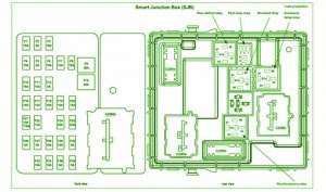
Fuse Box Ford 2006 SUV Diagram - Here are new post for Fuse Box Ford 2006 SUV Diagram.

Fuse Box Ford 2006 SUV Diagram


Fuse Box Ford 2006 SUV Diagram

Fuse Panel Layout Diagram Parts: trailer tow park lamp, park lamp, ignition switch, powertrain control module, fuel pump relay, main fan relay, passive anti theft system, high mounnted stop lamp, stop lamp, powertrain control module, brake pedal position switch, instrument cluster, diagnostic connector, power mirror switch, audio unit, canister vant, power seats, sunroof, compass, radio, power window, suwoofer, low eams, horn.

Towbar Wiring Fitting Guides

Posted by Unknown 0 comments
Trailer Wiring on Trailer Wiring
Trailer Wiring.


Trailer Wiring on Trailer Wiring Diagrams  Johnson Trailer Sales  Colfax Wisconsin
Trailer Wiring Diagrams Johnson Trailer Sales Colfax Wisconsin.


Trailer Wiring on Pn Trailer Wiring
Pn Trailer Wiring.


Trailer Wiring on Trailer Wiring Connector Diagrams For 6   7 Conductor Plugs
Trailer Wiring Connector Diagrams For 6 7 Conductor Plugs.


Trailer Wiring on Trailer Circuit Wiring
Trailer Circuit Wiring.


Trailer Wiring on Trailer Wiring Basics For Towing
Trailer Wiring Basics For Towing.


Trailer Wiring on How To Towbar Wiring 12n 12s Fitting Guides
How To Towbar Wiring 12n 12s Fitting Guides.


Trailer Wiring on Trailer Wiring Diagrams  Johnson Trailer Sales  Colfax Wisconsin
Trailer Wiring Diagrams Johnson Trailer Sales Colfax Wisconsin.


Trailer Wiring on Wiring Diagram For Bumper Pull Dump Trailers And Roll Off Dump
Wiring Diagram For Bumper Pull Dump Trailers And Roll Off Dump.


Trailer Wiring on Load Trail Trailer Wiring Plug Diagram
Load Trail Trailer Wiring Plug Diagram.


Skema Rangkaian Pengapian Motor CDI

Posted by Unknown 0 comments
The CDI ignition circuit produces a spark from an ignition coil by discharging a capacitor across the primary of the coil. A 2uF capacitor is charged to about 340 volts and the discharge is controlled by an SCR.

Skema Rangkaian Pengapian Motor - CDI

A Schmitt trigger oscillator (74C14) and MOSFET (IRF510) are used to drive the low voltage side of a small (120/12 volt) power transformer and a voltage doubler arrangement is used on the high voltage side to increase the capacitor voltage to about 340 volts.

A similar Schmitt trigger oscillator is used to trigger the SCR about 4 times per second. The power supply is gated off during the discharge time so that the SCR will stop conducting and return to its blocking state. The diode connected from the 3904 to pin 9 of the 74C14 causes the power supply oscillator to stop during discharge time. The circuit draws only about 200 milliamps from a 12 volt source and delivers almost twice the normal energy of a conventional ignition circuit.

High voltage from the coil is about 10KV using a 3/8 inch spark gap at normal air temperature and pressure. Spark rate can be increased to possibly 10 Hertz without losing much spark intensity, but is limited by the low frequency power transformer and duty cycle of the oscillator. For faster spark rates, a higher frequency and lower impedance supply would be required. Note that the ignition coil is not grounded and presents a shock hazard on all of its terminals. Use CAUTION when operating the circuit.

An alternate method of connecting the coil is to ground the (-) terminal and relocate the capacitor between the cathode of the rectifier diode and the positive coil terminal. The SCR is then placed between ground and the +340 volt side of the capacitor. This reduces the shock hazard and is the usual configuration in automotive applications.

Self Installation of Auto Sound System can Save Serious Cash

Posted by Unknown 0 comments
If you are seriously hoping to save a significant chunk of change when it comes to your auto sound system, you should consider saving on installation. Under ordinary circumstances I urge people to be very, if not overly cautious when it comes to installing your own auto sound systems. The thing is, that some people really are talented when it comes to activities such as this. Beyond talent, some people have frightening skills with electronics and if you are one of those, then by all means consider the money you could save yourself (or the extra money youd have to invest in your system?).


We all know that money doesnt grow on trees and when youve been saving up for quite a while to get the sound system you really want its a serious joy killer to have to wait another month or two in order to save up enough money to cover the cost of the installation of your sound system. If you or someone you know and trust (trust being the operative word in this instance) can do the work, it makes no sense from a fiscal point of view to pay someone else to do it.

That being said, if there are any doubts about your skill or experience you might want to at the very least get a second opinion or price installations in your area to see if it might actually be worth saving a little more. Time is another important issue when it comes to the installation of an auto sound system. It doesnt matter how capable you are of making the installation if you simply lack the time to do it. In cases such as this it would have been just as wise to go ahead and pay someone to make the installation. It makes much more sense to me than having the system sitting in a box for months on end while you wait for the time to get it taken care of.

I am one of those people who firmly believes that time is money. Time lost from work is expensive. This is especially true when the times of 10 or more people are lost. It adds up quickly no matter if you have a small or a large company. Time is also (unfortunately) the one commodity in life that you can never recover. No matter how hard you try you cannot recapture time that has been lost. If you have children you know exactly what Im talking about (particularly if your children are either teens or grown and gone). You cannot recover lost time so make sure you arent wasting your time by trying to install an auto sound system that is beyond your abilities.

Dont fret though. Most of us find that at some point in our lives we are limited by either time or money if not both. If everything was quick and easy we wouldnt really have anything worth working for would we? Consider all your limitations when planning and purchasing your auto sound system and make sure that the system you select falls squarely within your ability to install, your time limit for installation, or your price range for affording to pay for the installation. Whether you decide to do your own installation or have a professional installation of your auto sound system the prize is the superior sound quality you will be able to enjoy.

150 watts power amplifier circuit

Posted by Unknown 0 comments
Amplifier circuit is 150 watts power amplifier circuit is quite simple.
This circuit requires only 5 pieces of transistors as the main component of reinforcement. There is no equalizer option on this amplifier circuit because it can be said of this series is very simple, so do not you compare it with that sold in the market which are usually equipped with various sound system and equalizer settings. 


But to add to your collection circuit, this circuit is fairly easy and inexpensive to make and maybe one day you may need as a weak signal booster from your electronic circuit. Or you can also make this amplifier as an amplifier of high frequency signal from the output circuit animal repellent and I guarantee the results are very satisfactory.

150 watts power amplifier circuit


Power supply required is two-polarity power supply is + - 45 volts. Maximum power that can be obtained by this amplifier circuit is around 150 watts. As the volume control you can add potensio or variable resistor 10 Kohm in series at the input. Use dispasi loudspeaker with 150 watts power. Use a heatsink on the transistor-transistor driver loudspeaker or amplifier late as Q1 and Q2.

Dual Input Combining Stereo Line Amplifier

Posted by Unknown Monday, April 8, 2013 0 comments
This circuit takes two separate line-level stereo (L & R) signals and combines them into one stereo (L & R) output, thus avoiding the need to switch between two pairs of input signals. In the author’s application, it is used to feed the stereo audio from a TV receiver and a DVD player into an external amplifier. The need for the circuit arose because of a design peculiarity in the TV receiver. The TV has four A/V inputs and one A/V output. AV1-AV3 accept composite or S-video plus stereo audio inputs and these feed into the TV’s A/V output. AV4 accepts Component video (Y/Pb/Pr) plus stereo audio but unlike AV1-AV3, its audio (and video) signals are not fed to the TV A/V output. The Y/Pb/Pr input was chosen for use with the DVD player because of its superior video quality, while the audio was to be fed to an external amplifier for improved reproduction.
Circuit diagram:
stereo-line-amplifier-circuit-diagram
Dual Input-Combining Stereo Line Amplifier Circuit Diagram
However, manual switching was inconvenient, hence the genesis of this design. In use, the DVD player audio is fed in parallel to TV AV4 and to one input pair of the combining amplifier, while the TV audio output feeds the other input pair. The amplifier output goes to the external audio amplifier. There is no conflict between the two audio inputs because when AV4 (DVD player) is selected, there is no TV audio output. In all other modes, the DVD player is off. As shown, the circuit has a voltage gain of 1.5 times (3.5dB) but this can be altered as required by changing the two 15kW resistors. Input impedance is 10kW and the outputs are isolated from cable and amplifier input capacitance with 47W series resistors. The circuit can be powered from a regulated 12V DC plugpack.
Author: Garth Jenkinson - Copyright: Silicon Chip Electronics
Source : www.extremecircuits.net

STV9380 and STV9381 Vertical efficient

Posted by Unknown 0 comments

STV9380 and STV9381 is a vertical ic-out which very efficient, so it does not require cooling (heat sink) as the vertical ic is generally. This circuit works the same way as most other vertical ic, except at the amplifier end only. Amplifier section works at the end of class D (this is different to the generally vertical ic which working on a class AB). 

STV9380 and STV9381
STV9380 and STV9381
Vertical signal input by the "MODULATOR" changed its form to first become a form of "pulses" box before it is reinforced by the end of the transistor. Here transistor "amplifier end" work as like "switching transistor". Output result is a strengthening of which pulses of the box is then returned into regular shapes such as vertical signal using an LC fillter (capacitor and filter coil) . Requires IC supply voltage (+) 16V and (-) 16V STV9380 is able to produce pulses of the vertical 2.5 APP (Ampere pitch to peak) and STV9381 3 APP.

STV9380 and STV9381 Vertical efficient

LTC3588 1 Piezoelectric Energy Harvesting Power Supply Circuit

Posted by Unknown 0 comments
Here’s a design circuit of The LTC3588-1 is a piezoelectric energy harvesting power supply IC that integrates a low-loss full-wave bridge rectifier with a high efficiency buck converter to form a complete energy harvesting solution optimized for high output impedance energy sources such as piezoelectric transducers. This is the figure of the circuit;


LTC3588-1 can be configured to deliver four output voltages: 1.8V, 2.5V, 3.3V and 3.6V. In this table you can see how you need to configure the pins of the LTC3588-1 to obtain the specified voltage.  To select Low for D0, D1 the pin must be connected to GND and if you need to select high for D0, D2 the pin must be connected to VIN2. The maximum output current can be set up to 100mA. As you can see in this power schematic circuit the design of power supply is very easy and require few external components. A power supply circuit based on the LTC3588-1 IC offers many features like: 950nA Input Quiescent Current (Output in Regulation – No Load) , 450nA Input Quiescent Current in UVLO, 2.7V to 20V Input Operating Range, Integrated Low-Loss Full-Wave Bridge Rectifier, Up to 100mA of Output Current, Selectable Output Voltages, High Efficiency Integrated Hysteretic Buck DC/DC.

The LTC3588-1 IC can be used in many applications circuits like: Piezoelectric Energy Harvesting, Electro-Mechanical Energy Harvesting, Wireless HVAC Sensors, Mobile Asset Tracking, Tire Pressure Sensors, Battery Replacement for Industrial Sensors, Remote Light Switches.

Wire Harness Offer Kinds Wire Harness Condition

Posted by Unknown 0 comments
Wiring Harness on 1992 1995 Tbi Stand Alone Wire Harness
1992 1995 Tbi Stand Alone Wire Harness.


Wiring Harness on Fog Light Wiring Harness With Switch Kts  Fog Lamp Wire Harness Fit
Fog Light Wiring Harness With Switch Kts Fog Lamp Wire Harness Fit.


Wiring Harness on The Following Wiring Harness And Cable Routing Diagram Apply For
The Following Wiring Harness And Cable Routing Diagram Apply For.


Wiring Harness on Wire Harness Offer Many Kinds Of Wire Harness Used For Air Condition
Wire Harness Offer Many Kinds Of Wire Harness Used For Air Condition.


Wiring Harness on Wiring Harness And Cable Connection Diagram Here  Source  Manual
Wiring Harness And Cable Connection Diagram Here Source Manual.


Wiring Harness on Wiring Harness Mediumsue0074fig 27 1277 Jpg
Wiring Harness Mediumsue0074fig 27 1277 Jpg.


Wiring Harness on System And Wiring Harness Diagram  04  1996 Toyota Tercel Wiring
System And Wiring Harness Diagram 04 1996 Toyota Tercel Wiring.


Wiring Harness on Scene Ls1 Wiring   Ls1 Wire Harness   Ls1 Ls3 Ls7 Wiring   Ls1 Wiring
Scene Ls1 Wiring Ls1 Wire Harness Ls1 Ls3 Ls7 Wiring Ls1 Wiring.


Wiring Harness on Chrysler 300 Instrument Panel Wiring Harness Png
Chrysler 300 Instrument Panel Wiring Harness Png.


Wiring Harness on Linear Mp3 Dvd Radio Wire Plug Harness Vm9311ts Vm9410 Vm9311 Vm9511ts
Linear Mp3 Dvd Radio Wire Plug Harness Vm9311ts Vm9410 Vm9311 Vm9511ts.