Schematic | Circuit guide | Manual Wiring diagram | Electronic
Showing posts with label control. Show all posts

Bass and Treble Control without any IC and Transistor

Posted by Unknown Friday, December 20, 2013 0 comments
This low cost bass treble circuit consists of some capacitors, resistors, and two T/C pot for BASS and TREBLE control. this circuit can be made without even a veroboard. You just solder components as this circuit network is not so complex. It has only two-pin parts. Let’s take a look at he circuit diagram. Nothing to say about it, as it is so simple that a beginner level hobbyist can even understand and build this circuit.

Bass and Treble Control without any IC and Transistor

But there are some -ve points of this circuit which I must say, after giving you the circuit. As no external power supply, the O/P power is much lesser than I/P power, so volume decreases. The treble control doesn’t act as linear, it increases treble a lot in the end pot side

Bipolar Stepper Motor Control

Posted by Unknown Wednesday, October 9, 2013 0 comments
First, we want to explain how such a controller works and what’s involved. A bipolar motor has two windings, and thus four leads. Each winding can carry a positive current, a negative current or no current. This is indicated in Table 1 by a ‘+’, a ‘–‘ or a blank. A binary counter (IC1) receives clock pulses, in response to which it counts up or down (corresponding to the motor turning to the left or the right). The counter increments on the positive edge of the pulse applied to the clock input if the up/down input is at the supply level, and it decrements if the up/down input is at earth level.

Bipolar Stepper Motor Control circuit diagramThe state of the counter is decoded to produce the conditions listed in Table 2. Since it must be possible to reverse the direction of the current in the winding, each winding must be wired into a bridge circuit. This means that four transistors must be driven for each winding. Only diagonally opposed transistors may be switched on at any given time, since otherwise short circuits would occur. At first glance, Table 2 appears incorrect, since there seem to always be four active intervals. However, you should consider that a current flows only when a and c are both active. The proper signals are generated by the logic circuitry, and each winding can be driven by a bridge circuit consisting of four BC517 transistors.

table 1Two bridge circuits are needed, one for each winding. The disadvantage of this arrangement is that there is a large voltage drop across the upper transistors in particular (which are Darlingtons in this case). This means that there is not much voltage left for the winding, especially with a 5-V supply. It is thus better to use a different type of bridge circuit, with PNP transistors in the upper arms. This of course means that the drive signals for the upper transistors must be reversed. We thus need an inverted signal in place of 1a. Fortunately, this is available in the form of 1d.

table 2The same situation applies to 1b (1c), 2a (2d) and 2b (2c). In this case, IC4 is not necessary. Stepper motors are often made to work with 12V. The logic ICs can handle voltages up to 15 to 18 V, so that using a supply voltage of 12 V or a bit higher will not cause any problems. With a supply voltage at this level, the losses in the bridge circuits are also not as significant. However, you should increase the resistor values (to 22 kΩ, for example). You should preferably use the same power supply for the motor and the controller logic. This is because all branches of the bridge circuit will conduct at the same time in the absence of control signals, which yields short-circuits.

Treble Tone Control

Posted by Unknown Saturday, October 5, 2013 0 comments

The treble control works in a similar manner as the bass control elsewhere in this site, but contains several modifications, of course. One of these is the series network C1-C2– R1– R1 1. The d.c. operating point of IC3 is set with resistors R12 and R13. To ensure that these resistors do not (adversely) affect the control characteristics, they are coupled to the junction of R9 and R1 0. In this way they only affect the low-frequency noise and the load of the opamp. Their value of 10 kΩ is a reasonable compromise. The functions of switches S1– S3 are identical to those of their counterparts in the bass tone control; their influence is seen clearly in the characteristics.

Circuit diagram:

Treble_Tone_Control_Circuit_Diagramw

Treble Tone Control Circuit Diagram

Good symmetry between the left-hand and right-hand channels is obtained by the use of 1% versions of R1– R1 3 and C1, C2. The value of resistors R2– R1 0 is purposely different from that of their counterparts in the bass tone control. In the present circuit, the control range starts above 20 kHz. To make sure that a control range of 1 0 dB is available at 20 kHz, the nominal amplification is 3.5 (11 dB ). The control circuit draws a current of about ±10 mA.

Source : www.extremecircuits.net

Guide to the Power Circuit and Control Circuit of the Wound Rotor AC Induction Motor

Posted by Unknown Friday, August 2, 2013 0 comments
In certain exceedingly enormous type of industrial applications where a tremendous amount of power is required to drive a specific type of load too large for the ordinary type squirrel cage induction motors to carry, the most appropriately preferred type of motor for use with such extensively large demand of power application is another type of large capacity motor which has the capability to run with high starting torque immediately attainable all throughout starting from when the motor is just beginning to run from rest even while it is at loaded condition up to when the motor reaches its peak rated speed while also carrying the same amount of heavy load, which would also necessitate for this type of motor to possess the ability to run continuously at different variation of steps of speed levels while driving a very heavy load. This type of motor is known as the wound rotor induction motor.


This so-called wound rotor motor as the name implies is a type of AC induction motor which does not only have stator windings but is also equipped with rotor windings. The terminal ends of its rotor windings are externally connected to slip rings and brushes as part of the motor assembly where these rotor winding terminates to terminal ends which are wired externally and connected further to an isolated resistor bank which is a separate necessary component to accompany the intended function of the motor to serve its purpose as a one whole complete functioning unit. The separate resistor bank unit connected to the motors wound rotor can be externally switched on and off at different intervals of resistor branches in the resistor bank, thus providing multiple stages of speed levels and torque capacity with an acceleration rate faster than would an ordinary induction motor could accomplish for similar types of bulky load applications to be driven.

Another purpose of the resistor bank connected to the rotor winding is to facilitate for the reduction of the very high inrush starting current, considering that the type of application that the motor will be subjected to requires for the motor to start running at a very heavy load condition.

The resistor bank also serves to absorb the heat developed in the rotor winding which is necessary for the intended application of the motor which is to have the ability to effectively dissipate the heat generated in such extreme load conditions, because rapid heat build-up is an inherent characteristic of very large capacity motors operating at very high load condition from zero speed up to its rated maximum speed or even when running the motor in any continuous variation of speed level falling anywhere within the various stages of speed range of the motor.
Fig-1 below shows an electrical schematic diagram of a three phase power circuit of a wound rotor motor. As shown in the drawing, you will notice that the motor consists of a stator winding which is the stationary part of the motor while another component of the motor is the rotor winding which constitutes the rotating part of the motor.

The stator winding is directly connected to the three phase power supply which provides the source voltage to the motor. The main supply voltage is supplied to the primary side of the disconnect fuse on the three phase terminals L1, L2 and L3 where the fuse serves as an instantaneous interrupting means with rapid action that immediately detects line side power trouble and motor circuit problem such as over voltage, over current, short circuit or overloads. The Main Magnetic Contactor (MMC) is a magnetic motor starter which serves as the motor operation switch which is electrically activated and deactivated remotely with an external push button switch in the control circuit. The overload relay is another type of overload protection device which is directly concentrated in instantaneously detecting motor overload currents that once detected would instantly trip-off to open the control circuit in order to deactivate the main magnetic contactor (MMC) to isolate power flow from the main supply line voltage going to the motor in order to prevent the destruction of the motor.
Fig-1: Electrical Schematic Diagram of the Power Circuit of a Wound Rotor Motor
The secondary part of the wound rotor motor contains the rotor winding. Fig-1 above shows the rotor winding connected to a resistor bank which consists of three resistors per phase making up a total of nine resistors in the entire resistor bank network. There are correspondingly three branches of resistors in the resistor bank which consists of the first branch comprising R1-R2-R3 resistors, the second branch being R4-R5-R6, and finally the last branch contains R7-R8-R9 respectively. Each stages of resistor branches are provided with their own individual magnetic contactor switches with MC1 for the first resistor branch, then MC2 for the second resistor branch and finally MC3 for the third resistor branch. Each of these resistor branches are shorted individually by MC1, MC2 and MC3 according to an order of operational sequence relative to the efficient running of the wound rotor motor.

The single phase step down transformer is made available in Fig-2 above is an electrical schematic diagram of a common control circuit which illustrates how the wound rotor motor is operated to run from standstill until it reaches its rated speed. The power supply source voltage of the control circuit is taken directly from the step down transformer provided in the power circuit in Fig-1 above which shows the reference terminals RC and SC coming from the secondary part of the step down transformer from the power circuit. The proper sequence of operation of the wound rotor motor is directly dependent on the construction of the control circuit based on the intended sequence of operation for this particular wound rotor motor.

The start operation sequence in the control circuit in Fig-2 above begins with the closing of the start push button switch which permits power flow to the main magnetic contactor (MMC) provided that both the stop switch and the overload relay contacts are maintained closed at all times during the operation of the control circuit. The auxiliary open contact of the MMC which is connected in parallel to the start switch serves as the holding contact which maintains the MMC coil energized even after the human operator releases the start switch, this in turn provides continuous power flow to the control circuit which further proceeds in commencing the sequence of steps in the operation of the entire circuit of the wound rotor motor.


During the first stage of the operation of the wound rotor motor when power is connected to the primary stator of the motor, the secondary part or the rotor is firstly connected with maximum resistance with all resistors in the resistor bank network fully active which initially runs the motor at its lowest speed. The flow of electricity in the control circuit would then proceed through the closed contact of Timer 4 going down to the Timer 1 coil which upon reaching its specified time delay period would then activate contactor MC1 to short the first stage resistor branch R1-R2-R3 leaving only the second and third stage of resistor branches to remain active in the resistor network to act on the rotor winding which will eventually increase the speed of the motor to a partial 1/3 of its rated speed.

The activation of contactor MC1 achieves the next step of the operational sequence that closes one of the auxiliary contact of MC1 to energize the Timer 2 coil which upon reaching its specified time delay period would then energize contactor MC2 to short out the second stage resistor branch R4-R5-R6 leaving only the third resistor branch to remain active in the rotor winding which further increases the motor speed to 2/3 of its overall rated speed.

Then comes the last and final stage where the previously activated contactor MC2 energizes the Timer 3 which when its specified time delay period expires would then activate contactor MC3 to totally short out the rotor winding to the fullest without any resistor branches remaining active in the network that can connect to the rotor winding, this final stage brings the motor to run to its fullest rated speed.

The activation of contactor MC3 would then provide a holding contact with one of its auxiliary contact connected in parallel across the Timer 3 contact while maintaining the MC3 coil energized during the final stage of this operational sequence.

This last stage would also activate and maintain the Timer 4 coil which upon reaching its specified time delay period would then open the Timer 4 normally-closed contact to remove power to the coils of Timer 1, MC1, Timer 2, MC2 and Timer 3 in order to release the first stage contactor MC1 and second stage contactor MC2 from shorting out the first and second stages of resistor branches but while also maintaining only the last contactor MC3 to remain activated to maintain the rotor winding shorted out completely hence maintaining the motor to run at its rated full speed.

To interrupt the operation of the circuit, the only thing necessary to manually stop the motor is by pressing the stop switch which would totally remove power to the circuit at any time during the circuit is active no matter under which stage of speed intervals the motor is actively running in. Another interrupting means in the control circuit is the overload relay which automatically shuts down the circuit to immediately stop the motor in case over current is instantly detected at anytime during the motor is running.

How to Build a Dual Axis Solar Tracker System Mechanism and Control Circuit Explained

Posted by Unknown Sunday, May 26, 2013 0 comments

The circuit and the mechanism explained in this article may be considered as the easiest and perfect dual axis solar tracker system. 

The device is able to track the daytime motion of the sun precisely and shift in the vertical axis accordingly.

 The device also effectively tracks the seasonal displacement of the sun and moves the entire mechanism in the horizontal plane or in a lateral motion such that the orientation of the solar panel is always kept in a straight axis to the sun so that it complements the vertical actions of the tracker appropriately.


As shown in the figure, a relatively easy mechanism can be witnessed here. The solar tracker is basically mounted over a couple of stand with a central movable axis.

The pivotal arrangement allows the panel mounts to move on a circular axis over almost 360 degrees.

A motor gear mechanism as shown in the diagram is fitted just at the corner of the pivotal axis in such a way that when the motor rotates the entire solar panel shifts proportionately about its central pivot, either anticlockwise or clockwise, depending upon the motion of the motor which in turn depends on the position of the sun.

The position of the LDRs are critical here and the set of LDR which corresponds to this vertical plane movement is so positioned that it senses the sun light accurately and tries to keep the panel perpendicular to the sun rays by moving the motor in the appropriate direction through a definite number of stepped rotations.

The LDR sensing is actually accurately received and interpreted by an electronic circuit which commands the motor for the above explained actions.

Another mechanism which is quite similar to the above vertical setting, but moves the panel through a lateral motion or rather it moves the whole solar panel mount in circular motion over the horizontal plane.

This motion takes place in response to the position of the sun during the seasonal changes, therefore in contrast to the vertical movements; this operation is very gradual and cannot be experienced on a daily basis.

Again the above motion is in response to the command given to the motor by the electronic circuit which operates in response to the sensing done by the LDRs.

For the above procedure a different set of LDRs are used and are mounted horizontally over the panel, at a specific position as shown in the diagram.

How the Solar Tracker Control Circuit Functions

A careful investigation of the circuit shown in the diagram reveals that the whole configuration is actually very simple and straightforward. Here a single IC 324 is utilized and only two of its op amps are employed for the required operations.

The op amps are primarily wired to form a kind of window comparator, responsible for activating their outputs whenever their inputs waver or drift out of the predetermined window, set by the relevant pots.
Two LDRs are connected to the inputs of the opamps for sensing the light levels.

As long as as the lights over the two LDRs are uniform, the outputs of the opamp remain deactivated.

However the moment one of the LDRs senses a different magnitude of light over it (which may happen due to the changing position of the sun) the balance over the input of the opamp shift toward one direction, immediately making the relevant opamps output go high.

This high output instantly activates the full bridge transistor network, which in turn rotates the connected motor in a set direction, such that the panel rotates and adjusts its alignment with the sun rays until uniform amount of light is restored over the relevant set of LDRs.

Once the light level over the relevant LDR sets is restored, the opamps again become dormant and switch off their outputs and also the motor.

The above sequence keeps on happening for the whole day, in steps, as the sun alters its position and the above mechanism keeps shifting in accordance to the suns position.

It should be noted that two sets of the above explained circuit assemblies will be required for controlling the dual actions or simply to make the above discussed dual tracker solar system mechanism.

Parts List

R3 = 15K,
R4 = 39K,
P1 = 100K,
P2 = 22K,
LDR = Normal type with a resistance of around 10 K to 40K in daylight under shade and infinite resistance in complete darkness.
Op-amps are from IC 324 or separately two 741 ICs may also be incorporated.
T1, T3 = TIP31C,
T2,T4 = TIP32C,
All diodes are 1N4007
Motor = As per the load and size of the solar panel

Courtesy - Elector Electroniks India

CONSTANT BRIGNESS LED AND MUTE CONTROL ELECTRONIC DIAGRAM

Posted by Unknown Saturday, April 13, 2013 0 comments

CONSTANT BRIGNESS LED AND MUTE CONTROL ELECTRONIC DIAGRAM

The output power of the modules are approximately 220W to 250W into 8? and 350W to 400W into 4?. Complete documentation for the amplifier modules can be found in the documents listed below. AN-1850 LME49830TB Ultra-High Fidelity, High-Power Amplifier Reference Design Although the power supply design is specific to the amplifier modules the concepts and circuit design may be used for any power supply purpose. The power supply is an unregulated design with an option to allow connection to either 120V or 240V mains. The design uses toroidal transformers, a fully integrated bridge, and various rail capacitors for ripple voltage reduction, noise suppression, and to act as high current reservoirs. Additional circuitry to control inrush current on power up and power up/ down Mute control are also included.

The topics discussed inside the application note including the introduction, overview, schematic and design, power supply, additional circuit, inrush current control, mute control, constant brightness LED circuit, summary, and many more.

Contrast Control for LCDs

Posted by Unknown Thursday, April 11, 2013 0 comments
The adjustment control for the contrast of an LC-Display is typically a 10-k potentiometer. This works fine, provided that the power supply voltage is constant. If this is not the case (for example, with a battery power supply) then the potentiometer has to be repeatedly adjusted. Very awkward, in other words. The circuit described here offers a solution for this problem. 

The aforementioned potentiometer is intended to maintain a constant current from the contrast connection (usually pin 3 or Vo) to ground. A popular green display with 2x16 characters ‘supplies’ about 200 µA. At a power supply voltage of 5 V there is also an additional current of 500 µA in the potentiometer itself. Not very energy efficient either. Now there is an IC, the LM334, which, with the aid of one resistor, can be made into a constant current source. The circuit presented here ensures that there is a current of 200 µA to ground, independent of the power supply voltage. By substituting a 2.2-k? potentiometer for R1, the current can be adjusted as desired.

Circuit diagram:The value of R1 can be calculated as follows: R1 = 227x10-6 x T / I. Where T is the temperature in Kelvin and I is the current in ampères. In our case this results in:
R1 = 227x10-6 x 293 /
(200x10-6)
R1 = 333R

Note that the current supplied by the LM334 depends on the temperature. This is also true for the current from the display, but it is not strictly necessary to have a linear relationship between these two. Temperature variations of up to 10° will not be a problem however. This circuit results in a power saving of over 25% with an LCD that itself draws a current of 1.2 mA. In a battery powered application this is definitely worth the effort! In addition, the contrast does not need to be adjusted as the battery voltage reduces. When used with LCDs with new technologies such as OLED and PLED it is advisable to carefully test the circuit first to determine if it can be used to adjust the brightness.

Circuit diagram:
contrast-control-for-lcd-circuit-diagramw
Contrast Controller Circuit Diagram For LCDs

The value of R1 can be calculated as follows: R1 = 227x10-6 x T / I. Where T is the temperature in Kelvin and I is the current in ampères. In our case this results in:
  • R1 = 227x10-6 x 293 /
  • (200x10-6)
  • R1 = 333R
Note:
  • The current supplied by the LM334 depends on the temperature. This is also true for the current from the display, but it is not strictly necessary to have a linear relationship between these two. Temperature variations of up to 10° will not be a problem however. This circuit results in a power saving of over 25% with an LCD that itself draws a current of 1.2 mA. In a battery powered application this is definitely worth the effort! In addition, the contrast does not need to be adjusted as the battery voltage reduces. When used with LCDs with new technologies such as OLED and PLED it is advisable to carefully test the circuit first to determine if it can be used to adjust the brightness.
     
     
    http://www.ecircuitslab.com

Radio Control for toy car

Posted by Unknown Sunday, April 7, 2013 0 comments
Radio Control for toy car
Play toy cars controlled by radio signals is an interesting game. The much-loved toy cars children, plus a simple circuit would be ideal for toy cars. This series of families use traditional digital CMOS IC which requires a very small electric current, so it does not impose on the performance of the original toy cars.
In this system, radio signals emitted not continuously but only generated when the controller sends a command left / right or forward / backward, and even then only a radio frequency of an intermittent, so it is sending pulses of radio wave frequency.
Number of pulses sent represents a command is sent, the command GO is represented by 8 pulses, represented by 16 pulses LEFT, RIGHT DOWN 32 pulses and 64 pulses. Command sent to a combination of two orders once gus, which is a combination of command forward / backward and right / left, for example, could be sent forward command and left once gus, in this case the number of pulses sent is 24, which is the sum of the forward command command as much as 8 pulses and left as many as 16 pulses.
Once a command is sent, the system stops sending commands in a certain time lag, the lag time it takes the receiver circuit will have sufficient time to execute properly. Frequency pulses were visible on the right side of Figure 1.

How it works The transmitter
Radio signals generated by the oscillator circuit formed by transistors Q1 9016, the working frequency of the oscillator is determined by the crystal Y1 is worth 27.145 MHz. A very critical part of this oscillator circuit is T1, L1 and L2, which specifically dealt with separately at the end of this article.
Work of the oscillator is controlled by a NOR gate U2D 14001, while the output gate (pin 3) is worth 1 , the oscillator will work and transmit radio frequency 27.145 MHz, and at the output U2D value 0 the oscillator will stop working.
U2D NOR gate receives the clock signal from the NOR gates U2B. NOR gate CMOS type with the help of resistors R4 and R5 and capacitor C8 to form a low frequency oscillator circuit to control the clock shaper of existing digital circuits. Working from the clock generator is controlled via the input leg 6, the circuit will generate the input clock that is berlevel 0 .
NOR gate U2A and U2C form a latch circuit (RS Flip Flop), due to the influence of resistor R2 and capacitor C11 which is fed to pin 9 on U2C, when the circuit gets power supply output U2C must be 1 and U2A output (pin 3) to 0 . This situation resulted EUIS clock generator generating a clock U2B work and release the reset state of the enumerator 14 024 IC (U1), so that the U1 start chopping and 27.145 MHz oscillator circuit to send pulses of the clock generator frequency during work.
At the start chopping, all the output IC 14 024 enumerators in kedaan 0 , after chopping the 8 pulse output Q4 (pin 6) will be 1, after chopping 16 Q5 pulse output (pin 5) to 1 , after chopping 32 Q6 output pulse (pin 4) to 1 , after 64 counts pulses output Q7 (pin 3) to 1.
Outputs are used to control the voltage above 9 feet U2C through diode D1 and D2, as long as it remains one of the output value 0 then the plant U2B clock still works, it will continue until dankatode D2 D1 cathode to 1 so that the foot 9 U2C a 1 as well. This situation will lead to 3 feet U2A output to 1 , which stops the clock generator and reset U2B enumerator 14 024 danberhenti is sending pulses of frequency 27 145 MHz.
To generate the lag time for the receiver circuits have enough time to perform the command, used a series of 9014 Q2, the resistor R7 and capacitor C10. The magnitude of the delay time is determined by the value of R7 and C10. The switch to send the command forward / backward and to send the command left / right are two separate switches. Each switch has three positions, the center position means that the scalar does not send commands.
How It Works Recipients
Figure 2 is a recipient of a series of paired images dimobil toy, serves to receive signals from the transmitter to control the motor cars, so cars can move forward / backward and left / right. Transistor Q1 with the help of resistors; capacitors and T1 form as a series of 27.145 MHz radio signal receiver. T1 in series with a T1 is exactly the same used in the transmitter circuit, how to make it are discussed below.
Transistor Q2 perlangkapannya formed following a series of pulses to change the radio frequency received from the transmitter into the box pulses that can be accepted as a digital signal by the CMOS IC. Digital signal will be received as the clock had to be chopped by enumerator 14 024 IC (U2). Output of 14 024 would correspond to the number of pulses sent by the transmitter, forward command and left (which is used as an example in the discussion of the transmitter) is the pulse number of 24, the enumeration of these pulses resulted in 14 024 to be output Q4 = 1 , Q5 = 1, Q6 = 0 and Q7 = 0.
The received digital signal other than U2 used as counter clock IC 14 024 discussed above, is also used to move the 3 pieces of the time delay circuit to generate pulses which controls the sequence of work.
The first control pulse will appear after submission frequency pulse stopped because the lag time between sending the code, this pulse count function to record the results of 14 024 to 14 042 U3 (D Flip Flop), so that the final condition of 14 024 will be retained to control the motor. After the results were recorded for 14 024 14 042, 14 042 counter is reset by the second pulse, so that after the lag time counter counts up starting from 14 042 to 0 again.
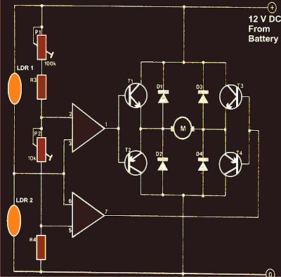
Circuit formed by transistors Q3, Q4, Q7, Q8, Q9 and Q10 H Bridge is named as a series, this series is very powerful to drive the DC motor. With this circuit the DC motor can be rotated to the right-to-left or stop motion. The main requirement is the use of this circuit Q7 and the base voltage of Q10 base voltage must be opposed, for example, the base Q7 = 1 and the base of Q10 = 0 motor rotates to the left, the base of Q7 = 0 and the base of Q10 = 1 motor will turning to the right, the base Q7 = 0 and Q10 base = 0 motor stop motion, but should not be happening base Q7 = 1 and the base Q10 = 1.
Similarly, Q5, Q6, Q11, Q12, Q13 and Q14 form an H Bridge. H Bridge to the left in Figure 2 is used to control a motor that regulates the movement of cars left / right, while the H Bridge to the right is used to control a motor that regulates the movement forward / backward cars.
The relationship between outpur enumerator 14 042 and input D Flip Flop 14 024 is arranged such that the signal is fed to each of the H Bridge can not be all 1 simultaneously.


Manufacture of transformer TX and RX
Transformer T1 in the series transmitter and receiver, is the same stuff, and have made ​​themselves. Transformer was built using a plastic transformer Koker (spare part radio) that has a step that appears 5 lines that can be filled with coils of wire, as shown in the photograph. Wearing this Koker facilitate wire transformer windings. Otherwise it could be similar Koker, just the usual wear. Koker is a small transformer and feritnya also small (3 mm) as that used to be used for the assembly of CB 27 MHz radio.
Can wear a wire to wire the transformer in the unloading of Koker, carefully open coil of wire that already exist in the Koker because the wire is quite smooth and quite easy to break.
Step 1: rolls of wire which is numbered 5 feet to 4 feet in the direction of h (CW) for 3 rolls right on level 1 (pathway level above the bottom line)
Step 2: Roll the wire from 1 foot to 2 feet in a clockwise direction as much as 4 rolls right on level 2.
Step 3: Continue the roll (from step 2) in a clockwise direction as much as three quarter roll to 3 feet on three levels. (Can be determined exactly a quarter of the roll, because it has a track kokernya split into 4).
Manufacture of coil L1
Roll of copper wire diameter from 0.3 to 0.5 mm by 10 quarter rolls on Koker diameter of about 4 mm (which will be released) is also in a clockwise direction.
Manufacture of coil L2
Roll of copper wire 0.1 mm diameter by 50 rolls in plastic Koker without ferrite diameter of about 3.5 - 4 mm (look for the plastic material from scrap) is also in a clockwise direction. Long section on liputi rolls along the 5 mm.